
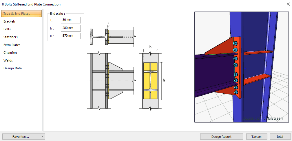
The 8 Bolts Stiffened End Plate Connection is a type of moment-transmitting connection (rigid connection), which is bolted to the columns and welded to the beam, and is a stiffening plate. Bolt control, weld control, plate control and connection application limits control are performed automatically according to the placement of the elements of the connection. The 8 bolts stiffened end plate connection design is made automatically according to the Design, Calculation and Construction Principles of Steel Structures (ÇYTHYEDY) or AISC 360-16 regulations and the connection report is created. Connection detail application limits are checked according to TBDY Table 9B.1.
In the calculation of the 8 Bolts Stiffened End Plate Connection, horizontal and vertical bolt distances, end plate weld thickness, continuity plate weld thickness and application limits are checked under geometry control. In strength checks, bolt diameter, end plate thickness, end plate shear yield, end plate shear failure, reinforcement plate weld thickness, slip on support bolts, bolt hole crush on end plate, bolt hole crush on column head, butt plate weld thickness, column head thickness, column panel zone slip and slip zone thickness control.
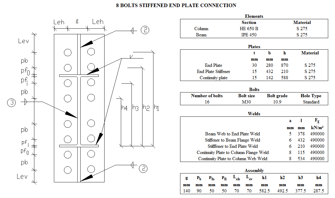
Connection Geometry
Geometry Checks
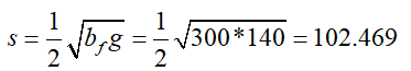
Bolt Spacing
|
smin ≥ 3d |
ÇYTHYEDY 13.3.6 |
|
|
|
s |
90 mm |
|
|
|
d |
30 mm |
s =90 mm > smin = 3*30=90 mm |
√ |
Horizontal Edge Distance
|
Leh ≥ Le- min |
ÇYTHYEDY 13.3.7 |
|
|
|
Leh |
60 mm |
L eh ≥ 2d = 2 * 30 = 60 mm conformity check for application |
√ |
|
Le- min |
40 mm |
Minimum distance check according to Table 13.9 |
√ |
Vertical Edge Distance
|
Lev ≥ Le- min |
ÇYTHYEDY 13.3.7 |
|
|
|
Lev |
60 mm |
L eh ≥ 2d = 2 * 30 = 60 mm conformity check for application |
√ |
|
Le- min |
40 mm |
Minimum distance check according to Table 13.9 |
√ |
Beam Web to End Plate Weld Size
|
a ≥ amin |
|
|
|
|
a |
5 mm |
|
√ |
|
amin |
3.5 mm |
Table 13.4 |
√ |
Stiffener to Beam Flange Weld Size
|
a ≥ amin |
|
|
|
|
a |
6 mm |
|
√ |
|
amin |
4 mm |
Table 13.4 |
√ |
Stiffener to End Plate Weld Size
|
a ≥ amin |
|
|
|
|
a |
6 mm |
|
√ |
|
amin |
4 mm |
Table 13.4 |
√ |
Continuity Plate to Column Flange Weld Size
|
a ≥ amin |
|
|
|
|
a |
8 mm |
|
√ |
|
amin |
4 mm |
Table 13.4 |
√ |
Continuity Plate to Column Web Weld Size
|
a ≥ amin |
|
|
|
|
a |
8 mm |
|
√ |
|
amin |
4 mm |
Table 13.4 |
√ |
Connection Detail Prequalification Limits (TBDY Table 9B.1)
|
Beam span / Beam cross-section height |
9144 mm /450 mm=20.32 |
≥7.0 |
|
End plate thickness, tp |
30 mm |
18≤t p ≤65 |
|
Flange plate width, bp |
298 mm |
215≤ b p ≤ 400 |
|
Horizontal distance between bolts, g |
154 mm |
125≤g≤155 |
|
pfi |
72 mm |
40≤p fi ≤50 |
|
pfo |
72 mm |
40≤p fi ≤50 |
|
Beam cross section height, db |
450 mm |
450≤ d b ≤ 950 |
|
Beam head thickness, tbf |
15 mm |
14≤t bf ≤35 |
|
Column cross section height |
650 |
≤ 920 mm |
|
Bolt class |
10.9 |
8.8 - 10.9 |
|
Min yield stress of the frontal plate material |
275 MPa |
235 /275/355 MPa |
|
Flange plate weld |
CJP |
CJP |
Strength Checks
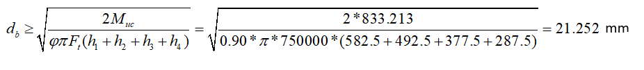
Bolt Diameter
|
Muc |
833.213 kNm |
AISC 358-16 (6.8-4) |
|
Ft |
750000 kN/m2 |
|
|
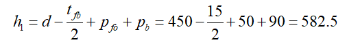
h1 |
|
|
|
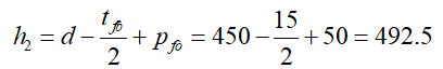
h2 |
|
|
|
h3 |
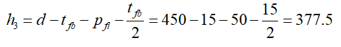
|
|
|
h4 |
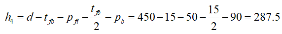
|
|
|
db |
|
|
|
Required |
Available |
Rate |
Control |
|---|---|---|---|
|
22.252 mm |
30 mm |
0.708 |
√ |
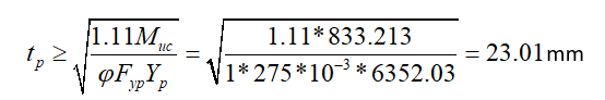
End Plate Thickness
|
Muc |
833.213 kNm |
AISC 358-16 (6.8-5) |
|
Fyp |
275000 kN/m2 |
|
|
s |
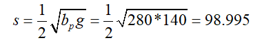
|
|
|
Yp |

|
|
|
Yp |

|
|
|
tp |
|
|
|
Required |
Available |
Ratio |
Control |
|---|---|---|---|
|
23.01 mm |
30 mm |
0.767 |
√ |
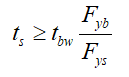
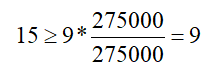
End Plate Stiffener Thickness
|
tbw |
9 mm |
AISC 358-16 (6.8-9) |
|
Fyb |
275000 kN/m2 |
|
|
Fys |
275000 kN/m2 |
|
|
ts |
12 mm |
|
|
|
|
|
|
|
|
|
|
Required |
Available |
Ratio |
Control |
|---|---|---|---|
|
9 mm |
15 mm |
0.600 |
√ |
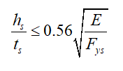
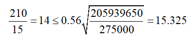
End Plate Stiffener Local Buckling
|
hs |
210 mm |
AISC 358-16 (6.8-10) |
|
ts |
15 mm |
|
|
E |
205939650 kN/m2 |
|
|
Fys |
275000 kN/m2 |
|
|
|
|
|
|
|
|
|
|
Required |
Available |
Rate |
Control |
|---|---|---|---|
|
14 mm |
15.325 mm |
0.914 |
√ |
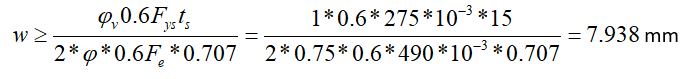
Stiffener to Beam Flange Weld Size
|
Fys |
275000 kN/m2 |
AISC DG 4-2nd 3.2.10 |
|
ts |
15 mm |
|
|
Fe |
490000 kN/m2 |
|
|
w |
|
|
|
Required |
Available |
Ratio |
Control |
|---|---|---|---|
|
7.938 mm |
8.487 mm |
0.935 |
√ |
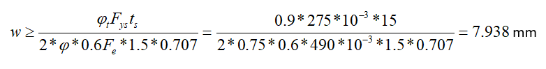
Stiffener to End Plate Weld Size
|
Fys |
275000 kN/m2 |
AISC DG 4-2nd 3.2.10 |
|
ts |
15 mm |
|
|
Fe |
490000 kN/m2 |
|
|
w |
|
|
|
Required |
Available |
Ratio |
Control |
|---|---|---|---|
|
7.938 mm |
8.487 mm |
0.935 |
√ |
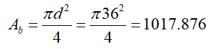
Bolt Shear at Support
|
Ab |
|
|
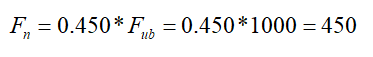
Fn |
|
|
Rn |
|
|
ΦRn |
|
|
Required |
Available |
Ratio |
Control |
|---|---|---|---|
|
211.464 kN |
2290.22 kN |
0.092 |
√ |
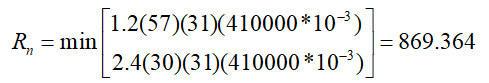
Bolt Bearing on End Plate
|
dh |
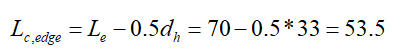
30+3=33 mm |
|
|
Lc,edge |
|
|
|
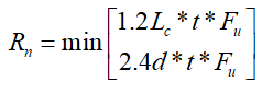
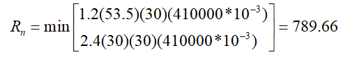
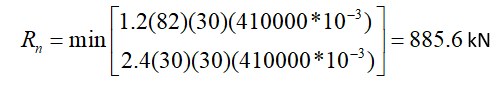
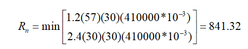
Rn |
|
ÇYTHYEDY 13.3.13 Equation 13.14a and13.14b |
|
Rn-edge |
|
|
|
Lc,spacing1 |
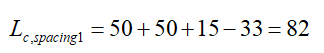
|
|
|
Rn-spacing1 |
|
|
|
Lc,spacing2 |
|
|
|
Rn-spacing2 |
|
|
|
Rn |

|
|
|
ΦRn |
|
|
|
Required |
Available |
Ratio |
Control |
|---|---|---|---|
|
211.464 kN |
6044.22 kN |
0.035 |
√ |
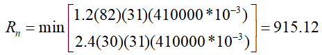
Bolt Bearing on Column Flange
|
dh |
30+3=33 mm |
|
|
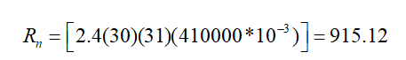
Rn |
|
ÇYTHYEDY 13.3.13 Equation 13.14a and13.14b |
|
Rn-edge |
|
|
|
Lc,spacing1 |
|
|
|
Rn-spacing1 |
|
|
|
Lc,spacing2 |
|
|
|
Rn-spacing2 |
|
|
|
Rn |

|
|
|
ΦRn |
|
|
|
Required |
Available |
Ratio |
Control |
|---|---|---|---|
|
211.464 kN |
6424.142 |
0.033 |
√ |
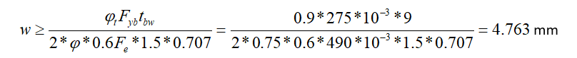
Beam Web to End Plate Weld Size
|
Fyp |
275000 kN/m2 |
AISC 358-16 (6.7.6) 3 |
|
tbw |
9 mm |
|
|
Fe |
490000 kN/m2 |
|
|
w |
|
|
|
Required |
Available |
Ratio |
Control |
|---|---|---|---|
|
4.763 mm |
7.072 mm |
0.673 |
√ |
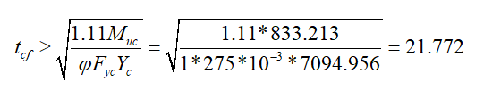
Column Flange Thickness
|
Muc |
803.836 kNm |
AISC 358-16 (6.8-13) |
|
Fyp |
275000 kN/m2 |
|
|
s |
|
|
|
c |
|
|
|
Yc |

|
|
|
Yc |

|
|
|
tcf |
|
|
|
Required |
Available |
Ratio |
Control |
|---|---|---|---|
|
21.772mm |
31 mm |
0.702 |
√ |
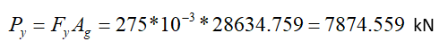
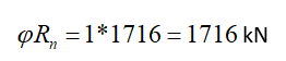
Column Panel Zone Shear
|
Pr |
429,124 kN |
ÇYTHYEDY 13.29a |
|
Py |
|
|
|
Fy |
275000 kN/m2 |
|
|
Ag |
28634.759 mm2 |
|
|
dc |
650 mm |
|
|
tw |
16 mm |
|
|
Rn |

|
|
|
ΦRn |
|
|
|
Required |
Available |
Ratio |
Control |
|---|---|---|---|
|
1696.742 kN |
1716 kN |
0.989 |
√ |
Panel Zone Thickness
|
t min ≥u / 180 |
|
TBDY 2018 9.3.4.2b |
|
tmin = t w |
16 mm |
|
|
tw |
16 mm |
|
|
u |
2016 mm |
|
|
Required |
Available |
Ratio |
Control |
|---|---|---|---|
|
11.2 mm |
16 mm |
0.700 |
√ |
Next Topic