-
Column, beam and curtain shear force demands are calculated automatically according to the performance point.
-
Ductility checks are made automatically by calculating the column, beam and shear strength capacities.
ICONS
A ch = Gross cross-sectional area of non-void wall, each wall segment in tie-beam wall, slab, or each slab piece in hollow slab
A w = Effective web area of column cross-section
b w = Body width ofbeam
d = Useful height of beam
f ck = Characteristic cylinder of concrete compressive strength
f yk = Characteristic yield strength of reinforcing steel
f ce = Average (expected) compressive strength of concrete
f ye = Steels of the average (expected) yield strength
M y = Effective yield moment of
V e = columns, beams and shear forces calculated thrust analysis result screen
V r = column shearing force of the beam or wall sections resistance
ρ sh = volumetric ratio of vertical rebars Curtain
θ p = Plastic rotation value
According to TDY 15.6 , the purpose of applying earthquake calculation with non-linear calculation methods is to calculate the plastic deformation and plastic rotation demands for ductile behavior and the internal force demands for brittle behavior for a given earthquake. Ductility checks for existing structures are made according to TDY 5.8.1.5 , taking into account the existing material strengths .
It is shown that the internal force demands calculated as specified in TDY 5.8.1.5 are smaller than the internal force capacities defined in TDY Chapter 7 . For new buildings, the average (expected) material strengths given in Table 5.1 are taken into account when calculating the internal force capacities .
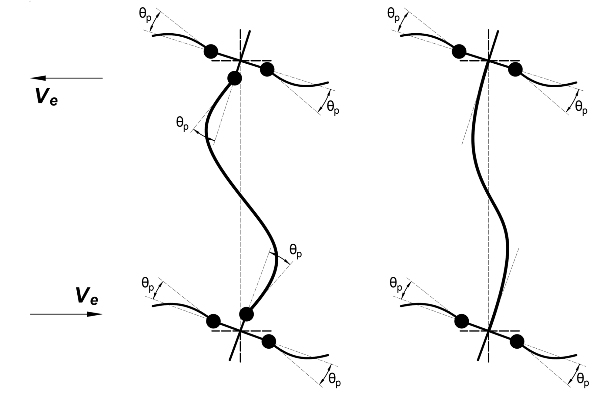
In order for the elements to show ductile behavior, no damage should occur under the effect of shear force. For this reason, the shear strength of the element must be greater than the shear force value that occurs in the formation of the plastic hinge. This shear force value is the shear force value at the performance point of the element. M resulting in the following manner with plastic on both ends of the beams Y , shearing force due to the torque V e is shown.
.png?cb=28fcc9b0930ed0550247d7767d67dafb)
The column shear force resulting beam lead and push analysis of the shielding member V e is shown. V e value is the value at the shear point performance. In the picture above, the shear forces in the beam as a result of beam plasticization are shown.
The shear force generated in the columns may vary depending on the beam or column plasticization. Column V e plasticized, which represents the value shown in the picture below.
Beam Shear Design Force available material strengths and Knowledge Level Coefficients are used.

Column Shear Design Forces available material strengths and Knowledge Level Coefficients are used.

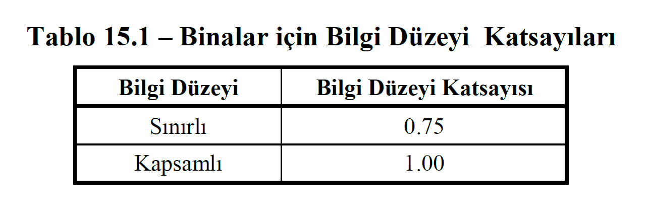
TDY 5.8.1.5 and 7.6.6.3 according to show the ductile behavior of a column, the shear force value occurs in column performance point V e 's, beam shear strength V r den must be small. Shear force strength on the curtains is found by V r TDY Equation 7.17 . Finding the shear strength V r is explained in detail under the heading Wall Design Shear Strength Calculation . For new building V r when calculating Table 5.1 'given the average (expected) material strengths are taken into account. V for existing buildingsWhen calculating r , the available material strengths and Information Level Coefficients given in Table 15.1 are used.


Information Level Coefficients used to calculate internal force capacities in existing buildings TDY Table 15.1 is given below