
-
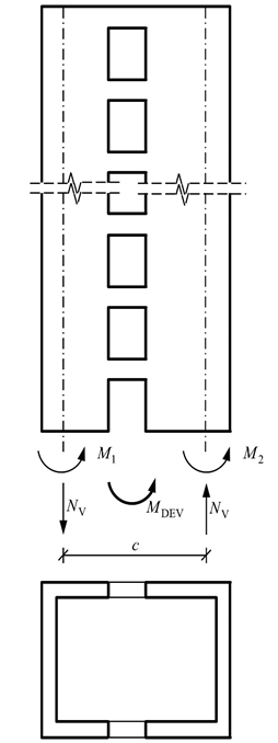
The Base Tipping Moment of tie-beam walls is calculated automatically using Equation 4.13 .
Symbols
c = The distance between the cross-section gravity centers of the tie beam (hollow) curtain parts
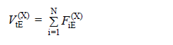
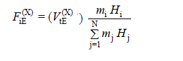
F iE (X) = (X) Equivalent earthquake load acting on the center of the i'th storey mass in the earthquake direction
H i = The i'th storey in the upper part above the basement floors of the building The height measured from the base of the upper section
M DEV = Tipping moment at the base of the reinforced concrete wall due to earthquake loads
M 1 = The bending moment obtained at the base due to the earthquake effect in the curtain parts forming the tie-beam curtain
M 2 =The bending moment obtained at the base due to the earthquake effect in the curtain parts forming the tie-beam curtain
m i = The total mass of the ith storey
N v = Equal tensile and pressure formed at the base of the curtain pieces as the sum of the shear forces formed in the tie beams of the bond beam curtain under the earthquake effect along the whole curtain height. axial forces
V tE (X) = (X) total equivalent earthquake load (base shear force) acting on the entire building in the earthquake direction
The base tipping moment of the bond beam (hollow) wall is calculated by the following equation:
Here, as the total tipping moment at the base of the wall with M DEV bond beam (hollow), the bending moments obtained at the base due to the earthquake effect in the curtain parts forming the wall with M 1 and M 2 bond beams, and N V as the sum of the shear forces in the bond beams under the earthquake effect, It corresponds to equal tensile and pressure axial forces formed at the base of the curtain parts. c shows the distance between the cross-section gravity centers of the curtain parts.
To use in the above equation , the p arameters M 1 , M 2 , N V and M DEV are calculated as follows:
-
The element group to be controlled with gaps is separated from the system, the inverted triangle unit loading is automatically distributed according to the weight of the floors . In this calculation, the value of the unit loading is not important, the curtain group and tie beams separated from the system take loads according to their own rigidity. In the automatic calculation, the force to be applied to the curtain group in total is determined. Then this force is distributed to each floor depending on its own weight using the following equations. The distributed force is applied to the center of the wall group and the parameters M 1 , M 2 , N V obtained as a result of this effect are replaced in the above equation.
Next Topic