
This message is created by specifying the element name and floor on which it is located at the beginning of the report.
For example,
SC001 BASE STORY Section dimensions do not conform toTBDY Table 9.3.
Width-to-thickness ratios of highly ductile beams and moderately ductile beams are checked in accordance with AISC 341-16 Table D1.1 and TBDY Chapter 9. Limit values of Width-to-thickness ratios λ hd or λ md are given in AISC 341-16 Table D1.1.
For detailed information, you can review the titles below.
Width-to-Thickness Ratios for SMF per AISC 341-16 with ideCAD
Solutions:
-
The cross-section of the steel element whose name and floor are given can be changed.
-
Steel beam cross-section selection can be made to reduce the header width/thickness or body height/thickness ratio.
-
If it is possible, a moderate ductility level can be selected.
AISC 341-16 Table D1.1 is given below.
|
Limiting Width-to-Thickness Ratios for Compression Elements for Moderately Ductile and Highly Ductile Members |
||||
|---|---|---|---|---|
|
Description of Element |
Width-to- Thickness Ratio |
Limiting Width-to-Thickness Ratio |
Example |
|
|
λhd
|
λmd
|
|||
|
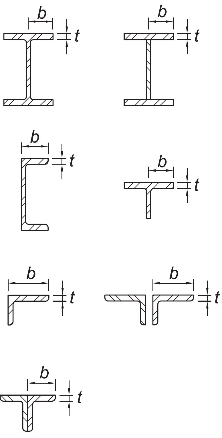
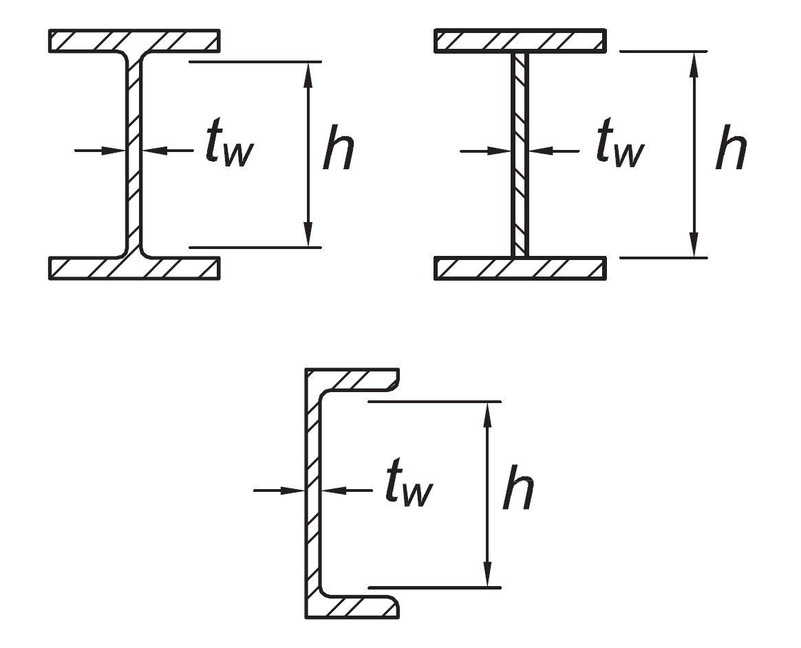
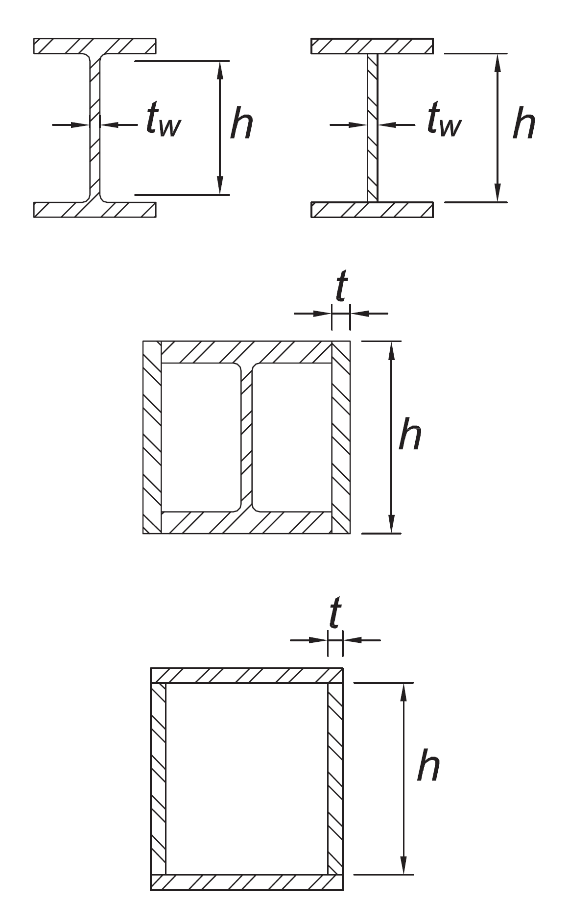
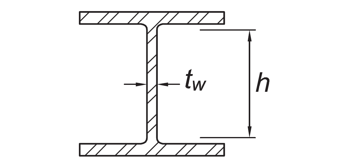
Flanges of rolled or built-up I-shaped sections, channels and tees; legs of single angles or double-angle members with separators; outstanding legs of pairs of angles in continuous contact |
b/t |
|
|
|
|
Flanges of H-pile sections per Section D4 |
b/t |
not applicable |
|
|
|
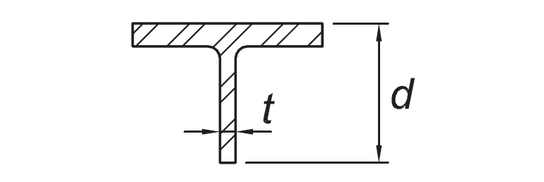
Stems of tees |
d/t |
|
|
|
|
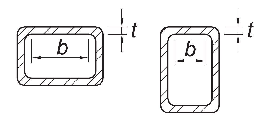
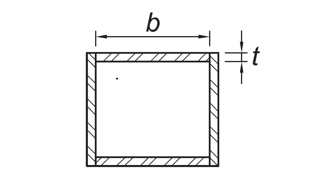
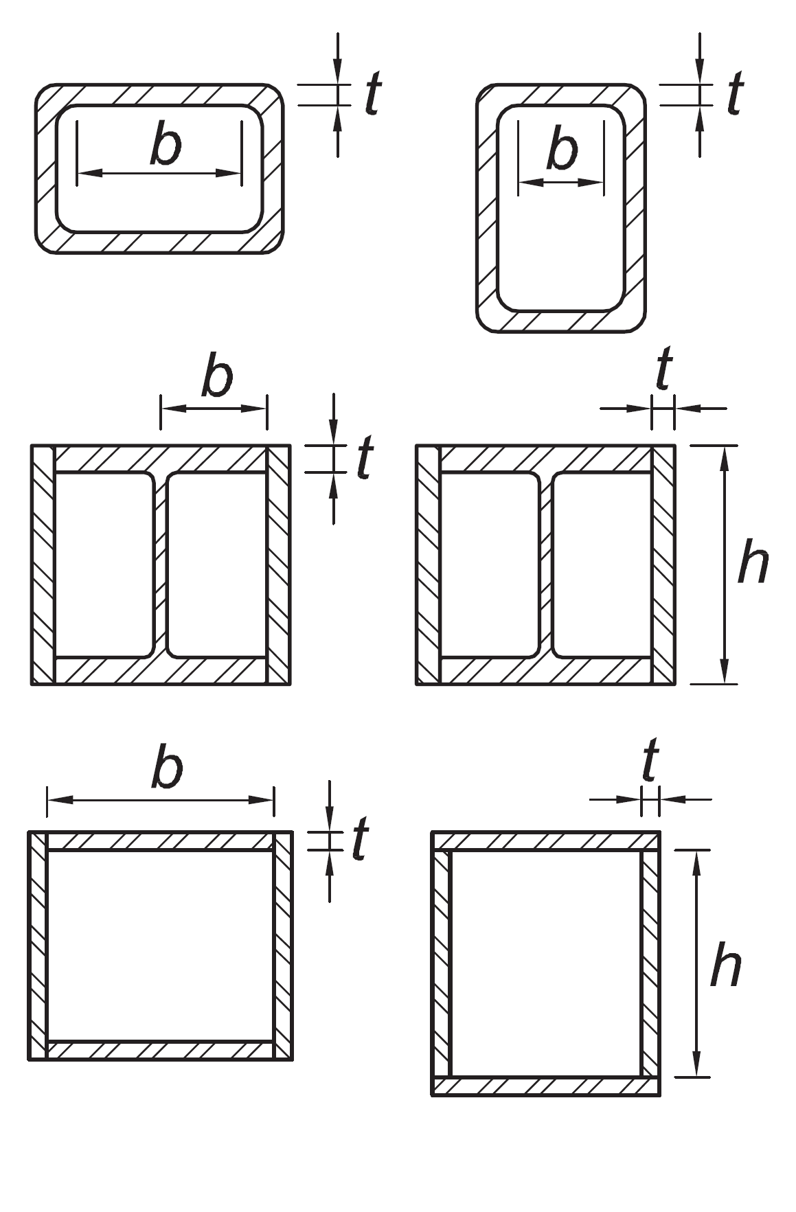
Walls of rectangular HSS used as diagonal braces |
b/t |
|
|
|
|
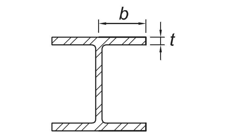
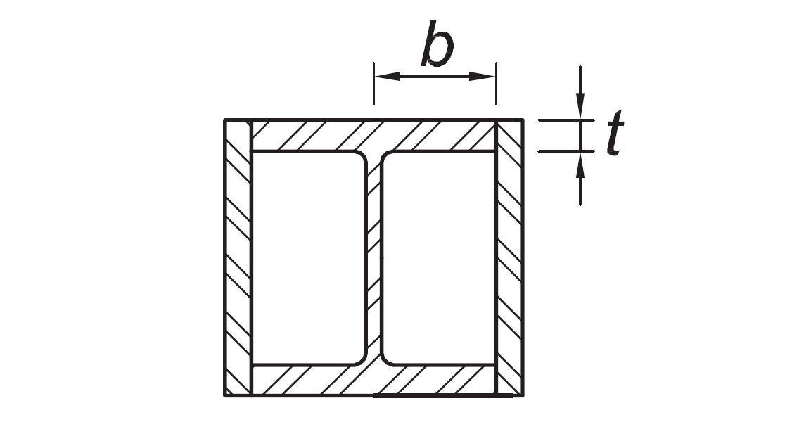
Flanges of boxed I-shaped sections |
b/t |
|
|
|
|
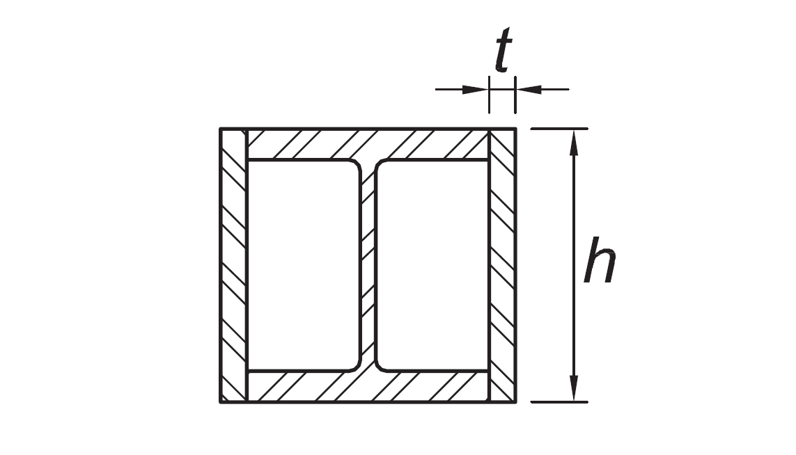
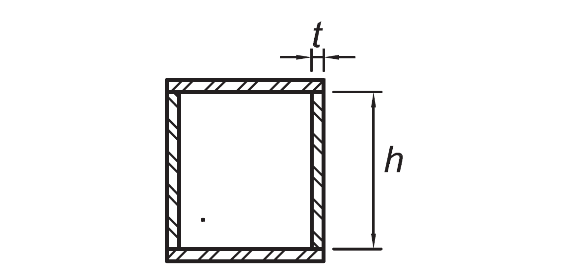
Side plates of boxed I-shaped sections and walls of built-up box shapes used as diagonal braces |
h/t |
|
|
|
|
Flanges of built up box shapes used as link beams |
b/t |
|
|
|
|
Webs of rolled or built-up I shaped sections and channels used as diagonal braces |
hw/t |
|
|
|
|
Where used in beams or columns as flanges in uniform compression due to axial, flexure, or combined axial and flexure:
|
b/t
h/t |
|
|
|
|
Where used in beams, columns, or links, as webs in flexure, or combined axial and flexure:
|
h/tw
h/t
h/t |
For Ca ≤ 0.114
For Ca > 0.114
where
|
For Ca ≤ 0.114
For Ca > 0.114
where
|
|
|
Webs of built-up box sections used as EBF links |
h/t |
|
|
|
|
Webs of H-Pile sections |
h/tw |
not applicable |
|
|
|
Walls of round HSS |
D/t |
|
|

|
Symbols
λhd : Limiting slenderness parameter for highly ductile elements
λmd : Limiting slenderness parameter for moderately ductile elements
Next Topic