
With the Unstiffened Seated Connection command, column-beam connection is defined.
Location of the Unstiffened Seated Connection Command
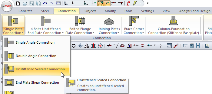
You can access it under the Ribbon menu, Connection tab, Connection title.
Usage Steps
If Draw in Fast Mode is Active
-
From the Connection menu, click on the Unstiffened Seated Connection icon.
-
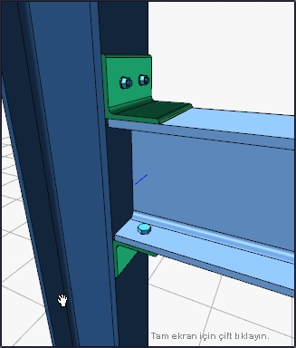
In 3D perspective view, move the mouse pointer closer to the element, close to the support
-
After this process, the virtual image of the connection will appear.
-
If the connection is suitable, create the connection by clicking the left mouse button.
-
The connection will occur with default settings.
If Draw in Fast Mode is Inactive
-
From the Connection menu, click on the Unstiffened Seated Connection icon.
-
Click the column then the beam before the 3D perspective view.
-
The unstiffened seated connection settings dialog will open.
-
The connection will occur when the wanted settings are made and the OK button is clicked.
Location of the Unstiffened Seated Connection Settings Dialog
If the draw in fast mode is active, the connection settings will be opened automatically.
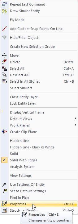
If the draw in fast mode is inactive, select the connection and click the right mouse button. Click the Properties line from the right click menu that opens.
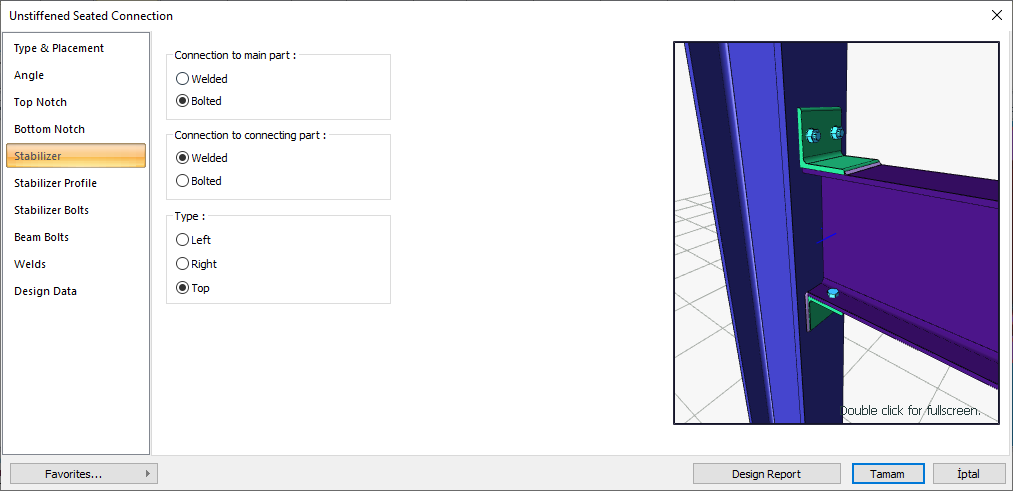
Unstiffened Seated Connection Settings Dialog
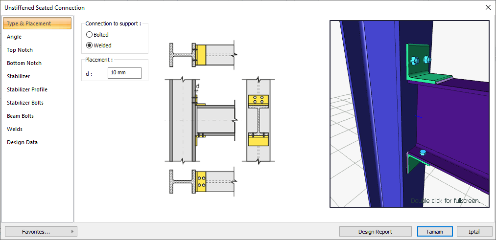
Type and Placement Tab
|
Specifications |
|---|
|
Connection to support 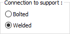
Bolted or welded connection types are selected for the support connection. |
|
Connection to beam 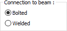
Bolted or welded connection types are selected for the beam connection. |
|
Placement Placement values are entered. The values to be entered are shown in the schematic drawing. |
|
Schematic drawing 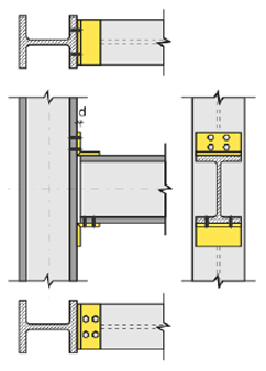
Connection and placement values are shown on the schematic drawing. |
|
Preview 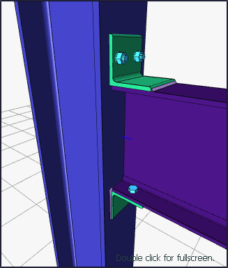
There is a preview of the connection. The selection made and the entered values can be followed simultaneously in the preview. |
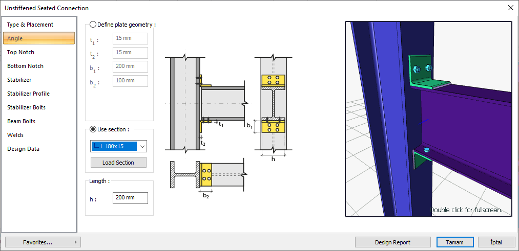
Angle Tab
|
Specifications |
|---|
|
Define plate geometry 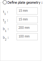
If the option is selected, it is determined by entering the angle values. The values to be entered are shown in the schematic drawing. |
|
Use section 
By selecting the option, one of the ready-made L profiles is selected from the list as an angle bracket. By clicking on the load section button, you can reach the ready section library and reach the list of American and European finished rolling sections and select from the list. |
|
Length 
Angle length value is entered. |
|
Schematic drawing 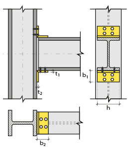
Connection and plate values are shown on the schematic drawing. |
|
Preview
There is a preview of the connection. The selection made and the entered values can be followed simultaneously in the preview. |
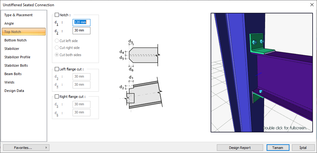
Top/Bottom Notch Tabs
|
Specifications |
|---|
|
Notch 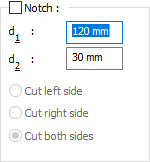
If the option is selected, notching is done according to the entered values. The values to be entered are shown in the schematic drawing. |
|
Left flange cut 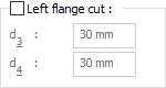
If the option is selected, left flange cutting is made according to the entered values. The values to be entered are shown in the schematic drawing. |
|
Right flange cut 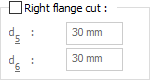
If the option is selected, right flange cutting is made according to the entered values. The values to be entered are shown in the schematic drawing. |
|
Schematic drawing 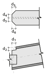
Connection, notching and cutting values are shown on the schematic drawing. |
|
Preview
There is a preview of the connection. The selection made and the entered values can be followed simultaneously in the preview. |
Stabilizer Tab
|
Specifications |
|---|
|
Connection to main part 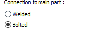
Bolted or welded connection types are selected for the main part connection. |
|
Connection to connecting part 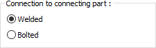
For the connected part connection, one of the bolted or welded connection types is selected. |
|
Type 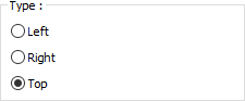
It is selected whether the connection will be on the left or right or on the top of the beam body. |
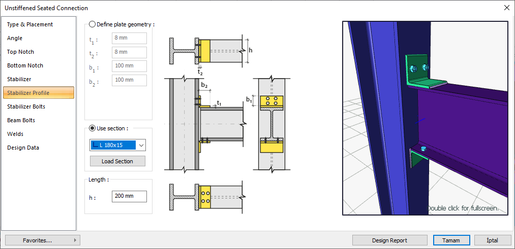
Stabilizer Profile Tab
|
Specifications |
|---|
|
Define plate geometry 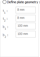
If the option is selected, it is determined by entering the angle values. The values to be entered are shown in the schematic drawing. |
|
Use section 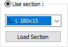
By selecting the option, one of the ready-made L profiles is selected from the list as an angle bracket. By clicking on the load section button, you can reach the ready section library and reach the list of American and European finished rolling sections and select from the list. |
|
Length 
Angle length value is entered. |
|
Schematic drawing 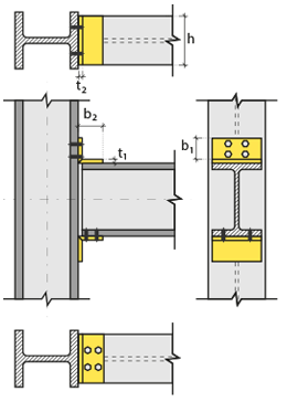
Connection and plate values are shown on the schematic drawing. |
|
Preview
There is a preview of the connection. The selection made and the entered values can be followed simultaneously in the preview. |
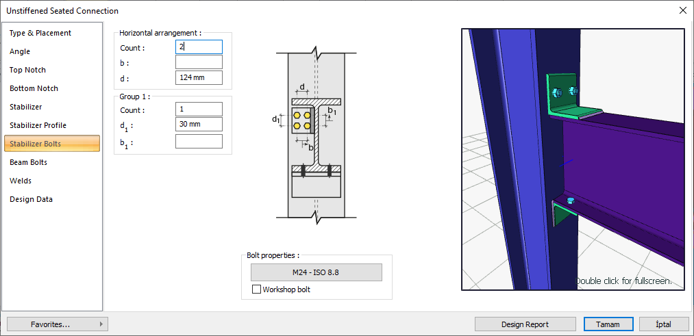
Stabilizer Bolts Tab
|
Specifications |
|---|
|
Horizontal arrangement 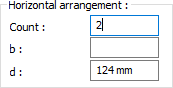
The horizontal arrangement settings (number of horizontal bolt columns, distance values ..) of the anchor bolts are entered. The values to be entered are shown in the schematic drawing. |
|
Group 1 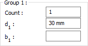
Stabilizer bolts settings (number of lines, distance values ..) are entered. The values to be entered are shown in the schematic drawing. |
|
Bolt properties 
The Hole and Bolt Parameters dialog is opened by clicking on the bolt properties button. The bolt properties are set in this dialog. |
|
Schematic drawing 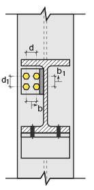
Connection and bolt placement values are shown on the schematic drawing. |
|
Preview
There is a preview of the connection. The selection made and the entered values can be followed simultaneously in the preview. |
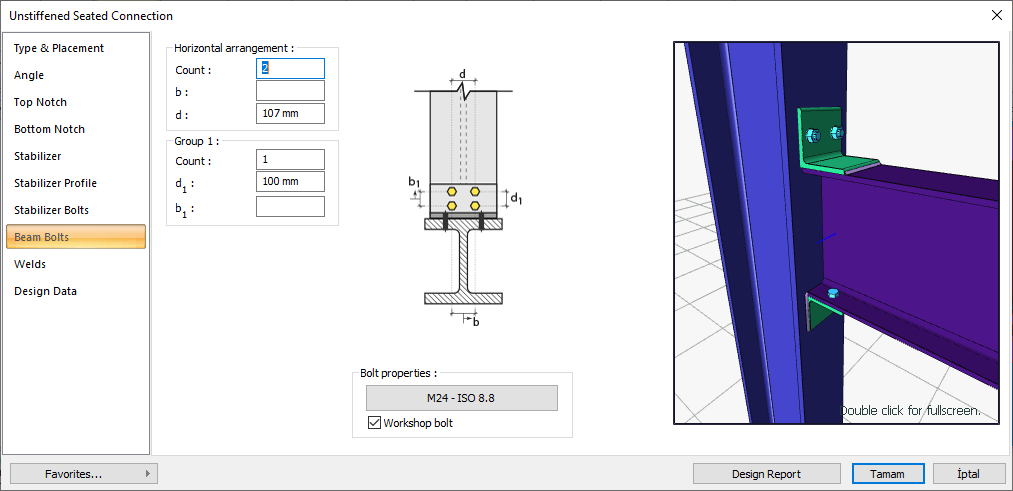
Beam Bolts Tab
|
Specifications |
|---|
|
Horizontal arrangement 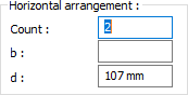
Beam bolts horizontal arrangement settings (number of horizontal bolt columns, distance values ..) are entered. The values to be entered are shown in the schematic drawing. |
|
Group 1 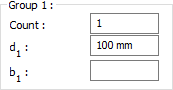
Beam bolts settings (number of lines, distance values ..) are entered. The values to be entered are shown in the schematic drawing. |
|
Bolt properties
The Hole and Bolt Parameters dialog is opened by clicking on the bolt properties button. The bolt properties are set in this dialog. |
|
Schematic drawing 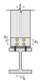
Connection and bolt placement values are shown on the schematic drawing. |
|
Preview
There is a preview of the connection. The selection made and the entered values can be followed simultaneously in the preview. |
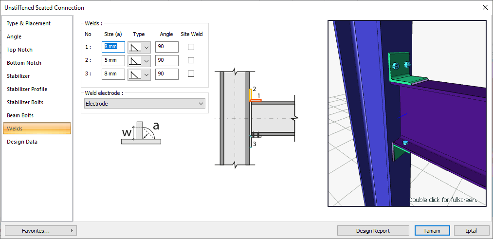
Welds Tab
In the welds tab, the weld properties of the connections given in the schematic representation are set.
|
Specifications |
|---|
|
Welds 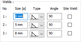
The thickness, type and angle values of the welds to be made at the connections are given. The information on whether it will be done on the construction site or not is entered. |
|
Weld electrode The strengths of the welding electrodes are defined in the design inputs. The strength of the main element in the weld joint is controlled under the condition that it has less strength than the weld strength. If necessary, click the list and define "Create New…". To create the welding electrode, give the information "Name" and "Weld metal tensile strength" in the dialog that opens after clicking "Create New". Welding geometry is determined automatically by the program. These properties can be changed to easily determine the connection properties. Geometry features are in accordance with industry standards and in the form specified in AISC. |
|
Schematic drawing 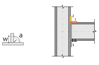
Connection and source values are shown on the schematic drawing. |
|
Preview 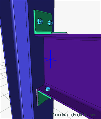
There is a preview of the connection. The selection made and the entered values can be followed simultaneously in the preview. |
Design Data Tab
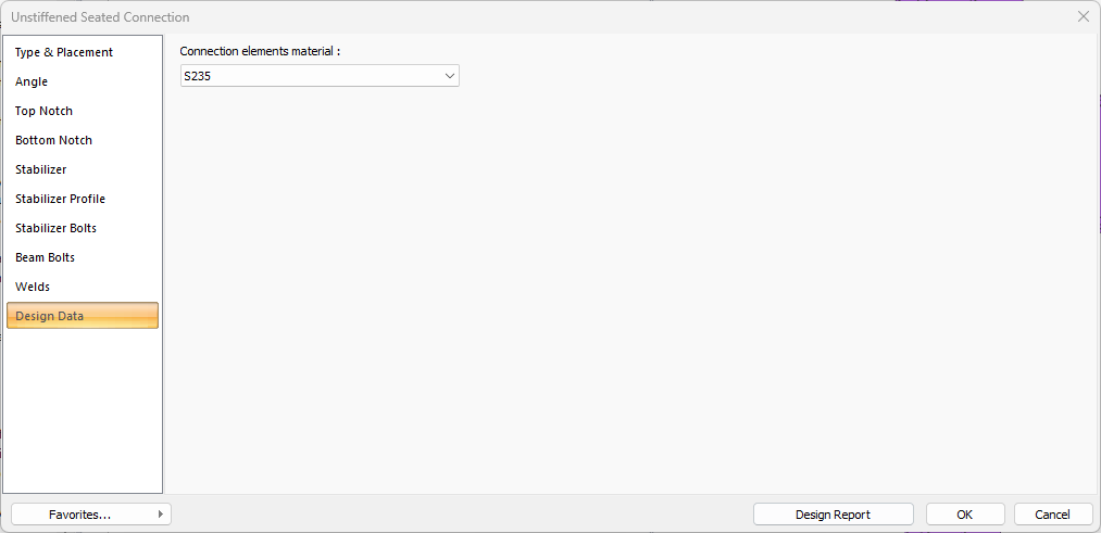
In the design data, the connection elements material is defined. The condition that the main element in the weld joint has less strength than the weld strength is controlled.
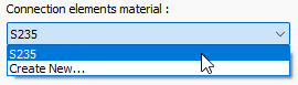
If necessary, click the list and define "Create New…". To create the connection elements material, give the information material definitions and values in the dialog that opens after clicking "Create New".
Next Topic