
ICONS
A w = Effective body area of column cross-section
f ck = Characteristic cylinder compressive strength of concrete
f cd = Design compressive strength of concrete
f yd = Design yield strength of longitudinal reinforcement
L n = Free height of column between beams, free span of beam between column or curtain faces
M a = Moment at the lower end of the column's free height, based on the column shear calculation
M ü =At the upper end of the column's free height, the moment
M hü (i) = The moment at the upper end of the column is the moment at the work floor.
M ha (i) = It is the moment at the lower end of the column at the work floor.
M ha (i + 1) = It is the moment at the lower end of the column in the upper floor of the studied floor.
M hü (i-1) = It is the moment at the upper end of the column in the lower floor of the studied floor.
M ra = The moment of bearing strength calculated according to f cd and f yd at the lower end of the free height of the column or curtain
M rü =The moment of bearing strength calculated according to f cd and f yd at the upper end of the free height of the column or curtain
M ri = The moment of positive or negative bearing strength calculated according to f cd and f yd on the column or wall face at the left end i of the beam
M rj = Negative or positive moment of bearing strength calculated according to f cd and f yd on the column or wall face at the right end j of the beam
V c = Contribution of the concrete to the shear strength
V e = Shear force based on column transverse reinforcement calculation
7.3.7. Shear Safety of Columns
7.3.7.1 - Shear force V e to be taken as basis for transverse reinforcement calculation in columns , Eq. It will be calculated with (7.5) .
V e = ( M a + M ü ) / l n (7.5)
For the calculation of M a and M u in Eq. (7.5) , if Equation (7.3) is fulfilled at the lower and / or upper ends of the column , 7.3.7.2 will be applied , and if not, 7.3.7.3 will be applied ( Figure 7.5 ). The sum of the shear force calculated from the earthquake increased with D with the vertical loads , Eq. If V e calculated by (7.5) is smaller than V e , this shear force will be used instead.
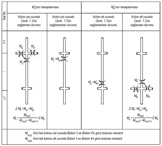
Figure 7.5 7.3.7.2 - The moment M p, which is the sum of the moment capacities at the ends of the beams joining to the joint point where Equation (7.3) is provided, will be calculated:
∑ M p = M pi + M pj (7.6)
In cases where a more precise calculation is not made, M pi ≈1.4 M ri and M pj ≈1.4 M rj can be taken. ∑ The moment M p will be distributed to the columns in proportion to the moments obtained according to Section 4 at the joining ends of the columns, and the moment obtained at the lower or upper end of the relevant column as a result of the distribution will be considered as M a or M u in Equation (7.5) . Equation (7.6) will be applied separately for both directions of the earthquake and the maximum obtained in each direction ∑ M p its value will be based on distribution.
Eq. (7.3) 'provided that although Eq. (7.5) ' one of M a or M ü 'are calculation, to stay on the safe side, 7.3.7.3 ' to be made to.
7.3.7.3 - The moments at the ends of the columns joining the node point where Equation (7.3) cannot be provided shall be calculated as the moment capacities of the columns and Equation. (7.5) 't M a and / or M ü will be used. Torque capacities, in cases where a more accurate analysis is performed, M pa ≈1.4 M ra and M pi ≈1.4 M r can be taken. In the calculation of M pa and M pü moments, in accordance with the direction of the earthquake, N d axial forces will be taken into account.
7.3.7.4 - Moment M a at the lower end of columns connected to the foundation shall also be calculated as moment capacities according to 7.3.7.3 .
7.3.7.5 - Shear force calculated by Equation (7.5) , V e , the shear force calculated under the combined effect of vertical loads and earthquake loads multiplied by the load coefficients shall not be taken less than V d and will also meet the conditions given in Eq. (7.7). . In case the second condition in Equation (7.7) is not fulfilled, the earthquake calculation will be repeated by increasing the cross-section dimensions as necessary.

7.3.7.6 - In the calculation of the column transverse reinforcement according to the shear force V e , the contribution of the concrete to the shear strength, V c , will be determined according to TS 500. However, in the calculation of the transverse reinforcement in the column confinement zones defined in 7.3.4.1 , if the shear force consisting only of seismic loads is greater than half of the total shear force under seismic condition and at the same time the condition N d ≤ 0.05 A c f ck is met, the contribution of concrete to shear strength is V c = 0 will be taken.
Next Topic