
With the Steel Joist Settings command, settings such as section, angle, elevation, placement, number of parts, material, drawing can be accessed.
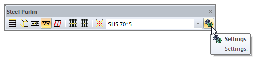
Location of Steel Joist Settings Command
It is located in the steel purlin toolbar that appears after the Steel Joist command is run.
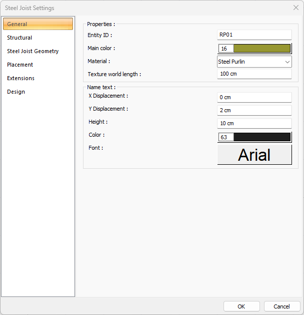
General Tab
|
Specifications |
|---|
|
Entity ID Space is the steel joists name that will appear in the plan, drawing and report. |
|
Main color It is the color of steel joist. It is scrolled on the color palette opened by clicking and holding the button with the left mouse button. When the desired color is reached, the button is released. The color box turns into the selected color. If clicked together with the Shift key, the pen thickness of the relevant color can be adjusted. |
|
Material In the solid model, the material to be coated can be selected. The element is overlaid with the selected material and displayed as such in the solid model. Click on the down arrow button with the left mouse button. The appropriate material is selected from the drop-down list of materials. |
|
Texture world length The texture length is entered. For example; If 1 meter is entered, the selected material texture width is taken as 1 meter and the selected object is overlaid. If the texture is considered to be square, the surfaces of the objects are covered with 1x1 textures lined up side by side. |
|
Name text - X/Y displacement X and Y coordinates of the steel joist dimension text are entered. If the size X value is entered positive, the text moves from the edge to the left, and if the negative value is entered, it moves to the right. If the text Y value is positive, the text moves up, and if it is negative, it moves down. The directions indicated here should be considered according to the direction of view. |
|
Name text - Height Dimension text height is entered. |
|
Name text - Color Size is the color of the font height. It is scrolled on the color palette opened by clicking and holding the button with the left mouse button. When the desired color is reached, the button is released. The color box turns into the selected color. If clicked together with the Shift key, the pen thickness of the relevant color can be adjusted. |
|
Name text - Font The font of the size text is selected from the dialog that opens when clicked. |
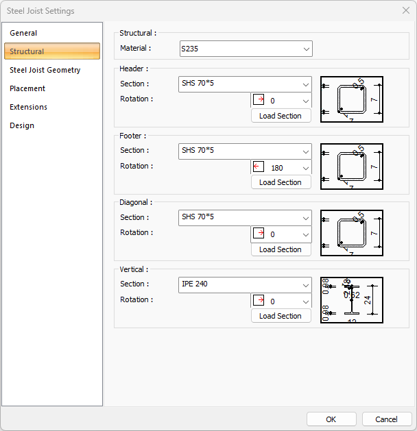
Structural Tab
|
Specifications |
|---|
|
Material The material for the steel joist is selected. |
|
Section list It is the list where the profile to be used for steel joist is selected. Separate section selections can be made for the header, footer. diagonal and vertical. The list includes steel profiles previously added from the profile library. |
|
Load section Click the Load Section icon to add a new profile. When clicked, the steel profile library is displayed. The profile to be used is selected from the list. |
|
Rotation The profile is created by rotating it around its axis according to a value selected as 0, 90, 180, 270. |
|
Schematic drawing 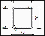
The schematic drawing and dimensions of the selected section are shown. |
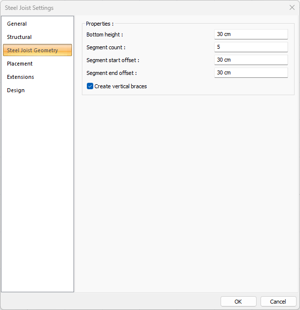
Steel Joist Geometry Tab
|
Specifications |
|---|
|
Bottom height The bottom height is entered. |
|
Segment count The number of steel joist pieces is determined. |
|
Segment start/end offset The distance of the pieces from the start and the end is determined. |
|
Create vertical braces If the option is checked, vertical braces are created. |
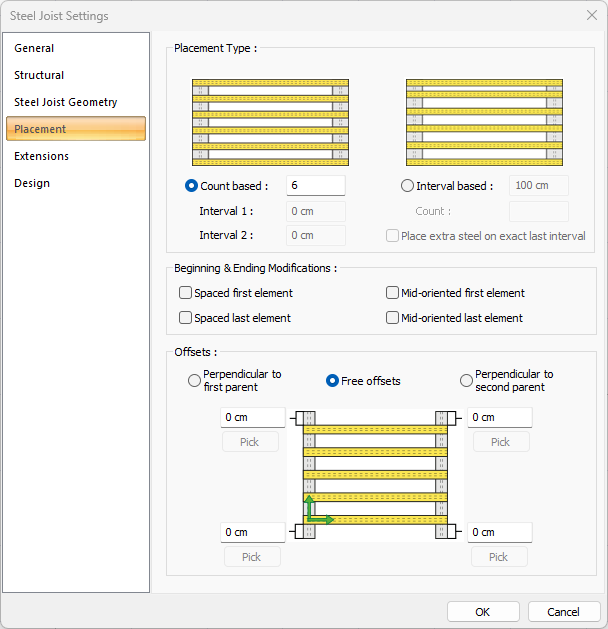
Placement Tab
|
Specifications |
|---|
|
Count based 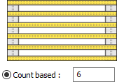
The steel joists can be drawn by entering a number. |
|
İnterval 1/2
It shows the distance between the steel joists. |
|
İnterval based 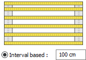
Steel joists can be drawn by entering the distance between the steel joists. |
|
Count Shows the count of steel joists. |
|
Place extra steel on exact last interval If selected, place extra steel on exact last interval. |
|
Spaced first element/Spaced last element 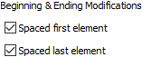
Since the first and last steel joist usually coincide on the element, they are options that can be used to eliminate this situation. If marked, steel joists found at the beginning and ending are not drawn. |
|
Mid-oriented first element/Mid-oriented last element When placing the first and last elements, alignment is made according to the midpoint of the element. When the Spaced first element/Spaced last element options are activated, these options become inactive. |
|
Offsets 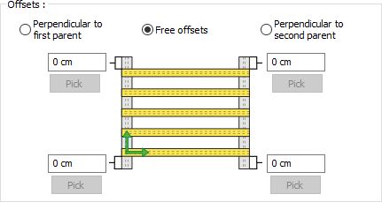
The start and end distances of the steel joists can be entered. If the options perpendicular to the first/second main part are marked, offset distances can be adjusted by keeping the perpendicularity condition constant to one of the main beams. If the free offsets option is selected, offset distances can be edited independently of the main beam parts. |
Extensions Tab
|
Specifications |
|---|
|
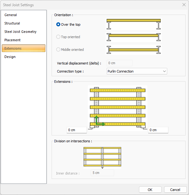
Over the top It enables the main elements, on which the steel joists are modeled, to be modeled to sit on the upper head. |
|
Top oriented It ensures that the upper head of the steel joist is aligned with the upper head of the main steel elements. |
|
Middle oriented It ensures that the middle point of the steel joists and the middle of the main steel elements are aligned. |
|
Vertical displacement (delta) The distance entered in the box allows modeling of the steel joist under the main steel element top head. |
|
Connection type 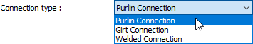
Select from the drop-down list for automatically generated slip connection between main steel element and steel joists. |
|
Extensions 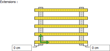
It determines how long the steel joists will be extended from the main elements. |
|
Inner distance 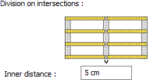
If the upper header option is used, the distance between the two purlin ends should be entered at the point where the steel joists touch the main elements. |
Design Tab
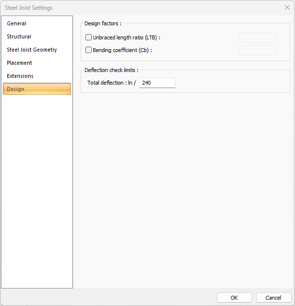
You can find detailed information on Steel Purlin Design Settings title.
Next Topic