
Settings such as elevation, length, rotation angle and material selection of 3D text/text created with 3d text settings are adjusted.
3D Text Settings Location
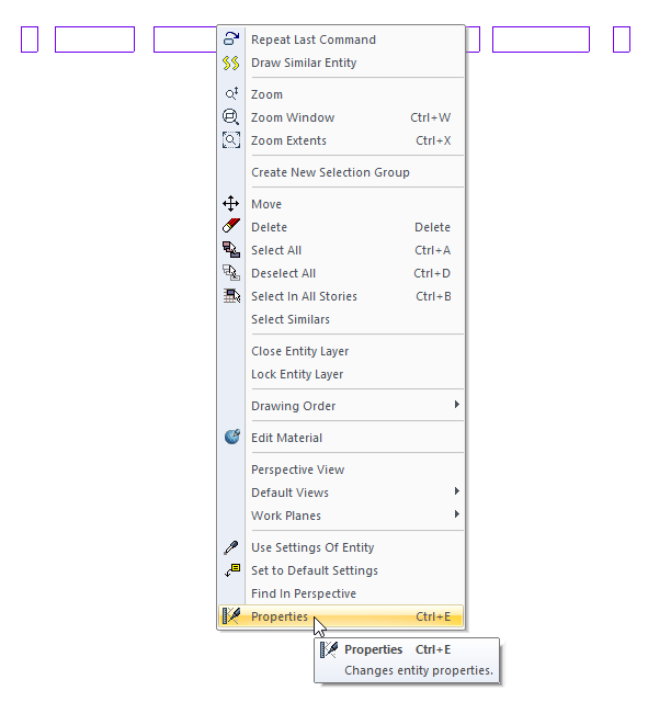
Select the 3D text and click the right button of the mouse and click the Properties line from the menu that opens, and you can access the settings of the 3D text.
Extended Item Tab
|
Specifications |
|---|
|
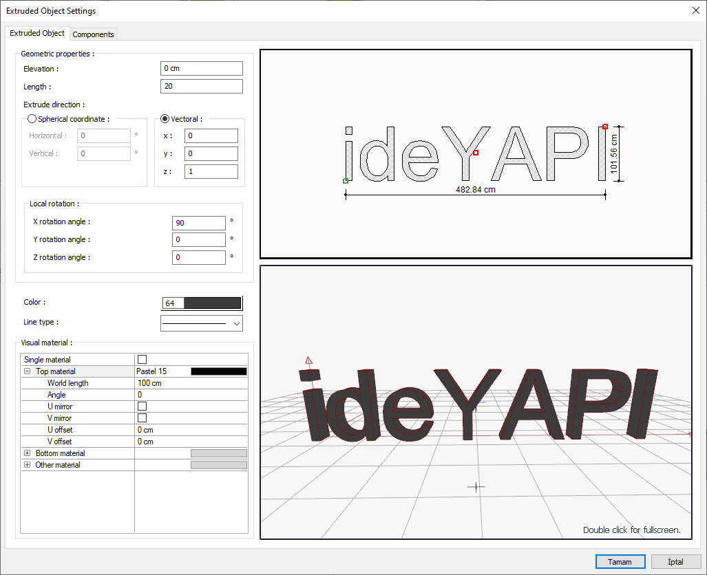
Elevation The level of the object is entered from the floor base. |
|
Length It is the elongation length of the 2 dimensional section defined in the plan. |
|
Spherical coordinate horizontal It is the angle that the axis makes with the horizontal (x-axis). |
|
Spherical coordinate vertical It is the angle that the axis makes with the vertical (z-axis). |
|
Vectoral x / y / z 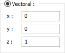
Values expressing the direction of the extension process in vector form. |
|
Local rotation x / y / z 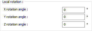
They are the values that determine the angle made by the section to be wrapped around the main axis according to its local axis. |
|
Color Choose the color of the object from the color palette that opens when clicked. |
|
Line type The line type of the line of the 3D text that appears in the plan is selected from the list that opens when clicked. |
|
Material appearance 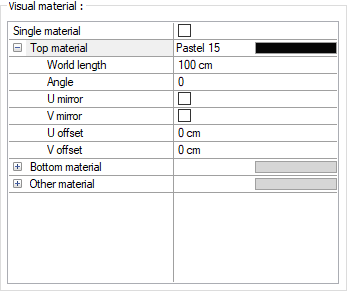
The material to be used on the top, bottom and other surfaces of 3D text is selected from the list. Surfaces are covered with the selected material and displayed as such in renderings. Texture length is entered into the world length. For example; If 1 is entered, the selected material texture is taken as 1 meter and covered on the relevant walls. The angle is the angle of the texture. Touch the U and V shifting. The motion value in the x and y plane is entered. With U and V mirroring, the texture is symmetrical with respect to the y and x plane. By selecting the single material option, the material selected in "Top material" is used on all surfaces of 3D text. |
|
Schematic drawing 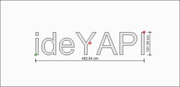
Includes a schematic drawing and dimensions of the 3D text. |
|
3D preview 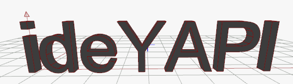
It is a 3-dimensional view of 3D text. You can rotate the image around itself by holding down the left mouse button and moving it. You can zoom in and out by holding the right mouse button and moving the mouse. |
Components Tab
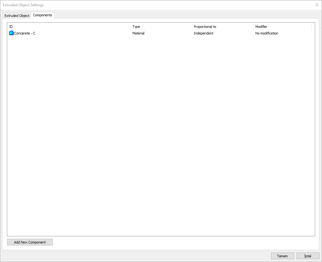
Add building components: Assigns the building materials defined for the detailed building components metering to the wall object.
-
Click the Add Building Component button.
-
The Component Selection dialog will open.
-
In this dialog, click the folder related to the material from the list on the left. Choose the material you want to use.
-
Set the parameters on the right.
-
Click the OK button. The "Component Selection" dialog will be closed. A summary line of the material will appear in the Building Components tab. More than one material assignment can be made to an object.
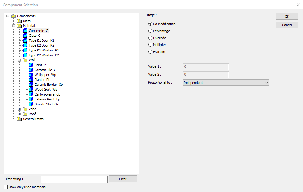
In the usage section
No modification: The amount of material to be assigned for the object in question is marked when it is desired to be used in the size that was previously specified in the material definition.
Percentage: This line is marked when it is desired to be used with the percentage of the amount previously determined in the material definition, as much as the value entered in the "Value 1" line in the same dialog. For example, if the material quantity is 70, if the line “Value 1” says 40, it means the material amount will be used up to 40 * 70%.
Override: This line is marked so that the quantity entered in the “Value 1” line in the same dialog will be used instead of the quantity previously determined in the material definition.
Multiplier: This line is marked in order to use the value found at the end of the multiplication of the value entered in the "Value 1" line in the same dialog with the amount previously determined in the material definition.
Fraction: This line is marked so that the amount determined in the material definition before will be used as the fraction value created by the values entered in the "Value 1" and "Value 2" lines in the same dialog. "Value 1" is the denominator "Value 2" is the denominator.
Proportional to: It is determined to what scale-area, circumference, length etc.-, region-side area, top, edge etc.- the material will be proportioned to. The content of the proportional list box is automatically determined according to the object and the size of the material. For example, a different list will be created if an operation is made for the column, a different list will be created for the library, a different list for the volume, and a different list for the field.
Following are the lines that appear in the proportion list according to the extruded object and material size.
|
Extruded Object |
||
|
Measure |
Listed |
Explanation |
|
Constant |
Independent |
The fixed measure used will be used exactly as the amount. |
|
Length |
Independent |
It means that the length measure found while defining the material will be used exactly as the length value. |
|
Length |
It means that the length of the material will be found by multiplying the length measure found when defining the material and the length of the object. |
|
|
Area |
Independent |
It means that the area measure found while defining the material will be used exactly as the field value. |
|
Area |
By multiplying the area measure found while defining the material with the area of the roof, the area of the material will be found. |
|
|
Volume |
Independent |
It means that the volume measurement found when defining the material will be used exactly as the volume value. |
|
Volume |
It means that the volume measure found when defining the material will be multiplied by the object volume. |
|
|
Count |
Independent |
The number measure found while defining the material will be used exactly as the number value. |
|
Count |
The number measure found while defining the material will be used exactly as the number value. |
|
Related Topics