
-
Punching stresses and stapling strengths are automatically calculated depending on the earthquake effects that are increased by the D coefficient together with the vertical loads in beamless floors and non-beam slab foundations.
-
With rectangular, round and polygon columns, the punching perimeter at the curtain ends is automatically calculated in accordance with TS 500 , taking into account the floor gaps .
-
Punching equipment and column head options are at the user's discretion.
-
When the column head is used, punching stresses and punching strengths are automatically calculated accordingly.
-
The punching stresses are automatically calculated according to the situations where the punching reinforcement is used properly distributed wedge or stand reinforcements or closed stirrup strips or sliding wedge rails are used in two perpendicular directions.
-
Without girders of the floor plate to column connection is taken into account in the system upper and torques which compensate the bending moment at the bottom of the column section and balanced torque coefficient γ f is automatically calculated.
-
The sum of polar inertia and second moments in the strong and weak axes of the surfaces forming the punching area (A z ) is automatically calculated in accordance with any type of column geometry.
Download ideCAD for ACI 319-19
ICONS
A wp = Total cross-sectional area of the vertical punching rebars on the punching circumference
A z = Punching area
b 1 = Punching circumference length in the loading direction
b 2 = Punching circumference length perpendicular to the loading
c (maj) = The center of gravity of the punching area calculated in the moment direction around the strong axis
c (min) = center of gravity calculated in the direction of the moment around the weak axis of the punching area
c ' (maj) =The center of gravity of the punching area calculated in the opposite direction of the moment around the strong axis
c ' (min) = The center of gravity calculated in the opposite direction of the moment around the weak axis of the punching area
d = Slab useful height
D = Strength Excess Coefficient
f ctd = Design tensile strength of concrete
J (maj) = Sum of polar inertia and second moments around the strong axis of the surfaces forming the stapling area (A z )
J (min) = Punching area (A z)) the sum of the polar inertia and second moments around the weak axis of the forming surfaces
M d (maj) = The design moment calculated under the combined effect of vertical loads and earthquake loads on the strong axis of the column and based on the slab punching calculation
M d (min) = In the weak axis of the column, vertical loads and earthquake loads and the design moment based on the slab punching calculation
u p = Punching circumference
V d = Punching force based on the punching calculation
τ pd, 1 = Design-based punching stress
τ pd, 2 =Punching stress based on design
γ v = Coefficient reflecting the shear effect in the punching calculation
γ f = Coefficient reflecting the bending effect in the punching calculation
ρ = Cross section area of the punching reinforcement in the unit area
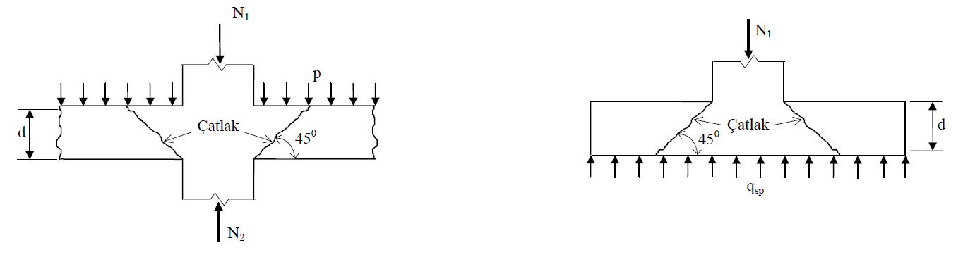
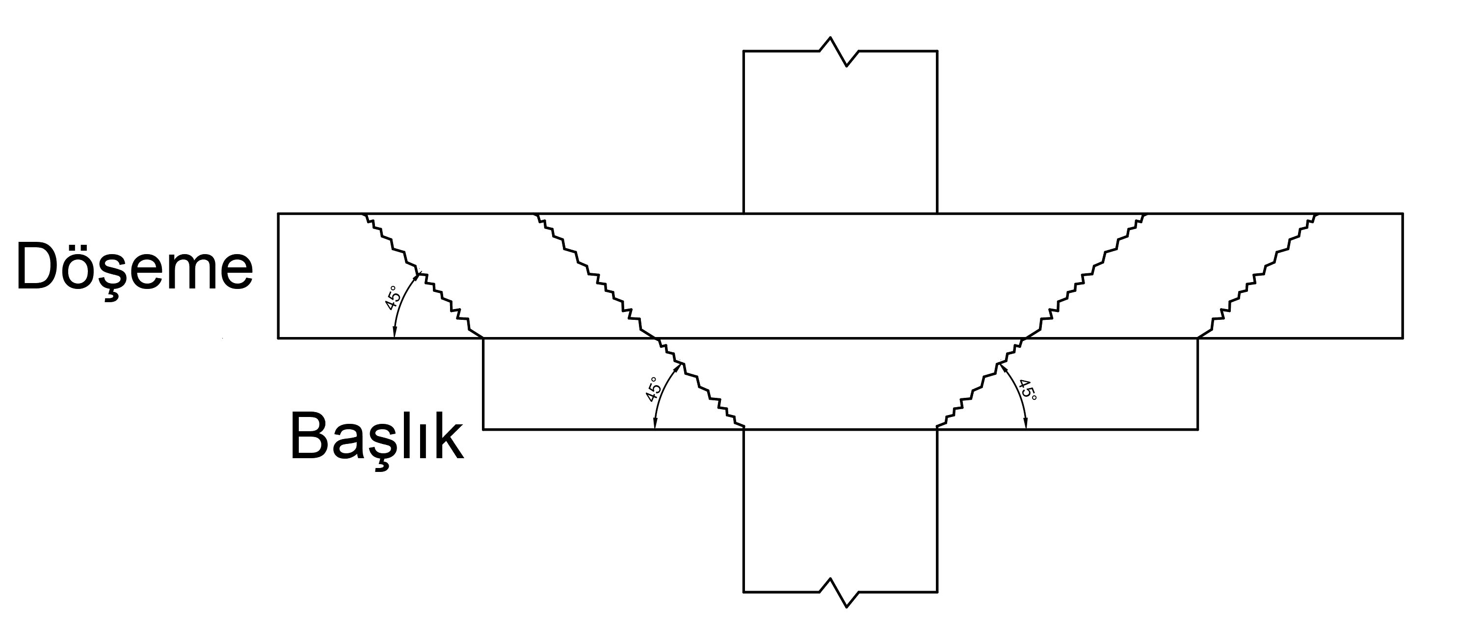
In non-beam slab systems where floors are directly supported by columns and in areas where raft foundations are connected to columns, principal tensile stresses occur around the column. When these principal tensile stresses around the column exceed the tensile strength of the concrete, it is natural that cracks occur perpendicular to the principal tensile stresses. Since the principal tensile stresses generally make an angle of 45 o to the plane of the plate , cracks will also occur at an angle of 45 o . With the formation of cracks, the strength of the concrete carrying the shear force is greatly reduced, so it punches the column, slab or raft foundation slab. Punching control according to TBDY is done with the following steps.
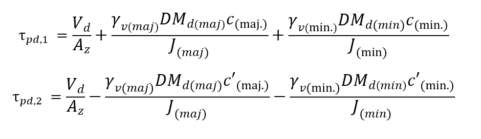
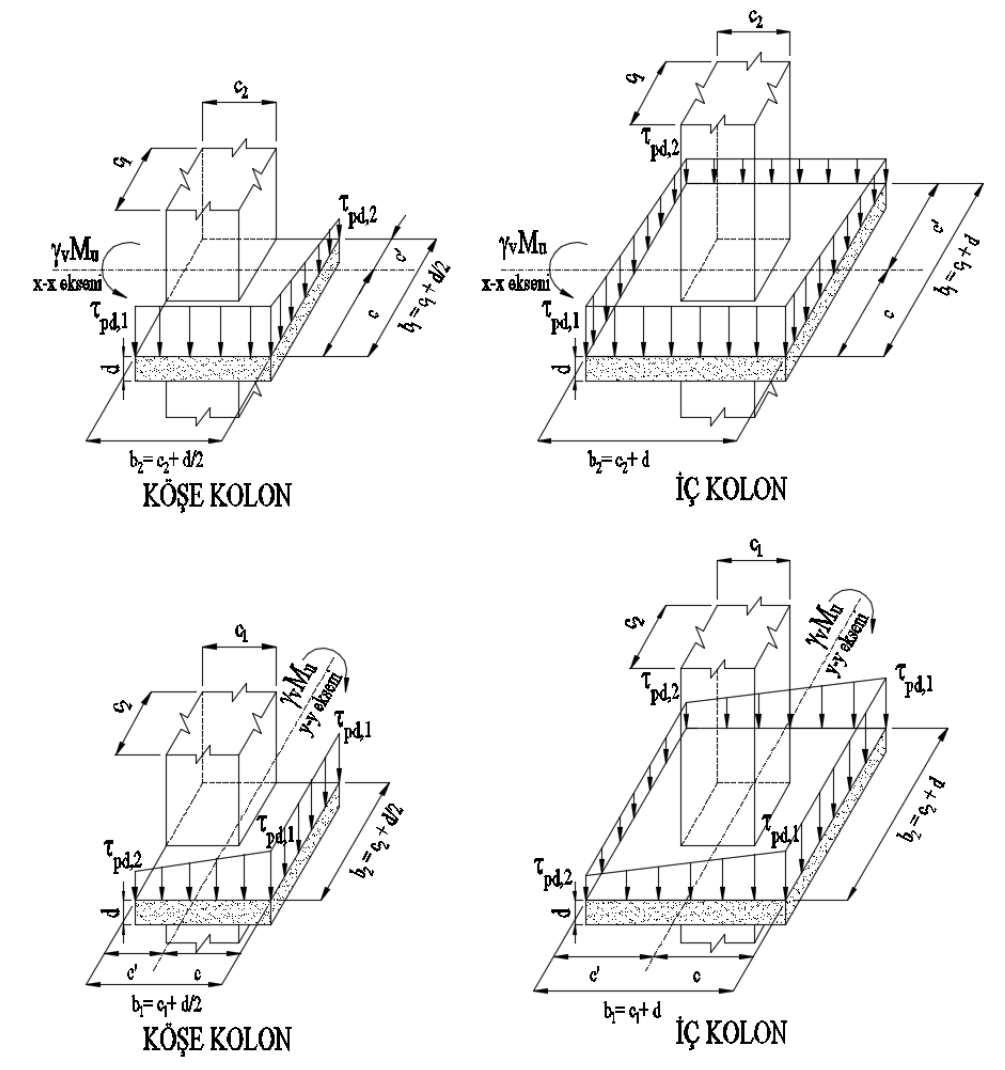
According to Article 7.11.8 of TBDY , assuming that the shear stresses in the slab change linearly according to the geometric center of the punching circumference in the loading direction, the shear stresses acting on the slab along the punching perimeter (u p ) can be calculated. The highest shear stress value calculated by this method is used as the design basis slab punching stress τ pd value. This punching stress occurs at two different values due to the moment effect as shown in the figure below. Therefore, torque in the direction of the tensile stress τ pd 1 , while stretching in the direction opposite τ pd 2 is named.
τ pd, 1 , τ pd, 2 : Refers to the punching stresses based on the design. Considering the effect of axial forces and bending moments, the slab is the largest and smallest punching stresses and is calculated with the equations shown below.
The absolute value of the punching stresses (τ pd, 1 , τ pd, 2 ) made according to all loading combinations is the design tensile strength (f ctd) of the concrete. should not exceed the ) value of the .
τpd,1 , τpd,2 ≤ fctd
The presence of punching stresses and terms in the formular are described below, respectively.
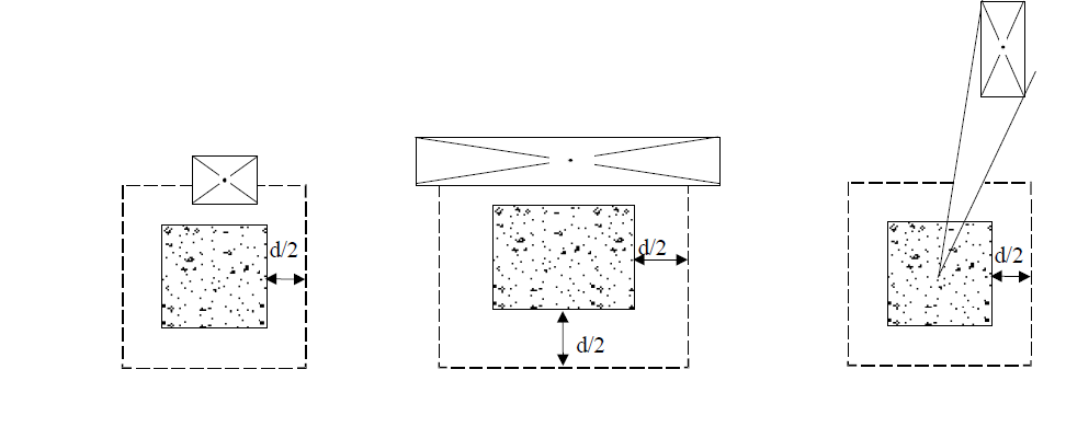
The punch perimeter (u p ) is the perimeter at d / 2 distance from the column surfaces and this perimeter is used in calculating the punching strength. D, which expresses the useful height of the slab, is obtained by subtracting the mat of the slab from the slab thickness. The punching perimeter in a sample square column is taken as follows in slab and slab foundations.
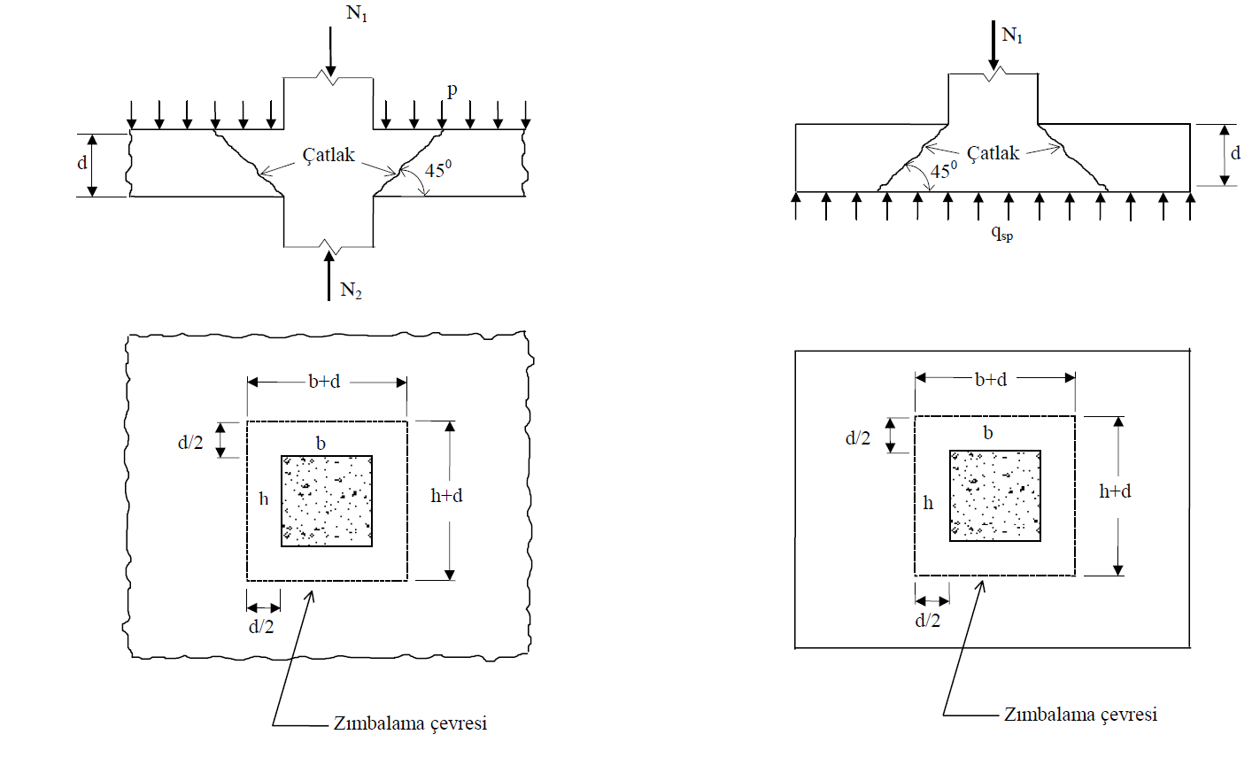
TS500 Figure 8.4 is considered for punching circumference in different situations . If there is a floor space d / 2 from the column surface, this space is removed from the punching perimeter. The following figure shows the situations where the floor space coincides with the punching perimeter.
The punching perimeter (u p ) for curtain or group walls is calculated in the curtain end zone in accordance with TS500 Section 8.3.1 . The punching perimeter in the curtain end region is calculated at a distance d / 2 from the outer surface and a distance a 1 from the end of the curtain as shown in the figure below. The lower value is taken into account by comparing the values a 1 distance is half the length (h) of the wall or curtain column and three times the wall thickness (b).
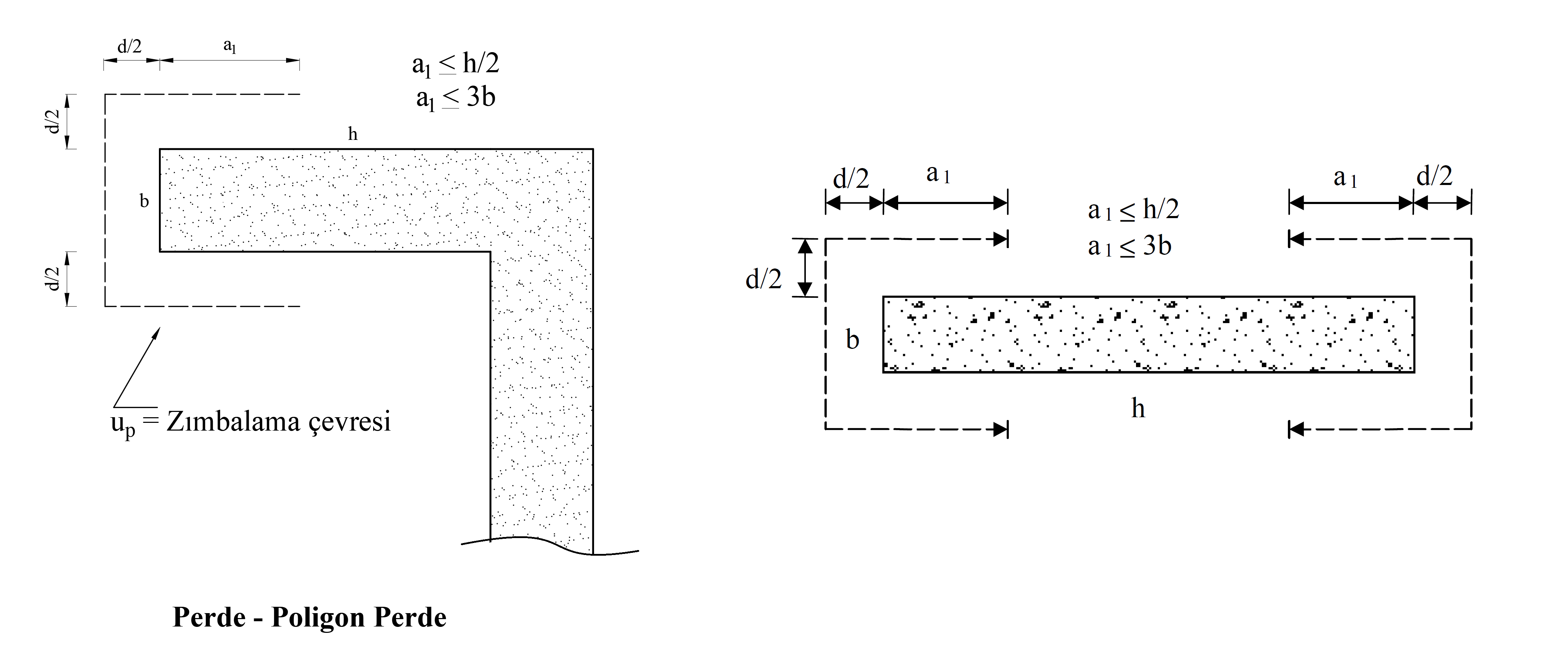
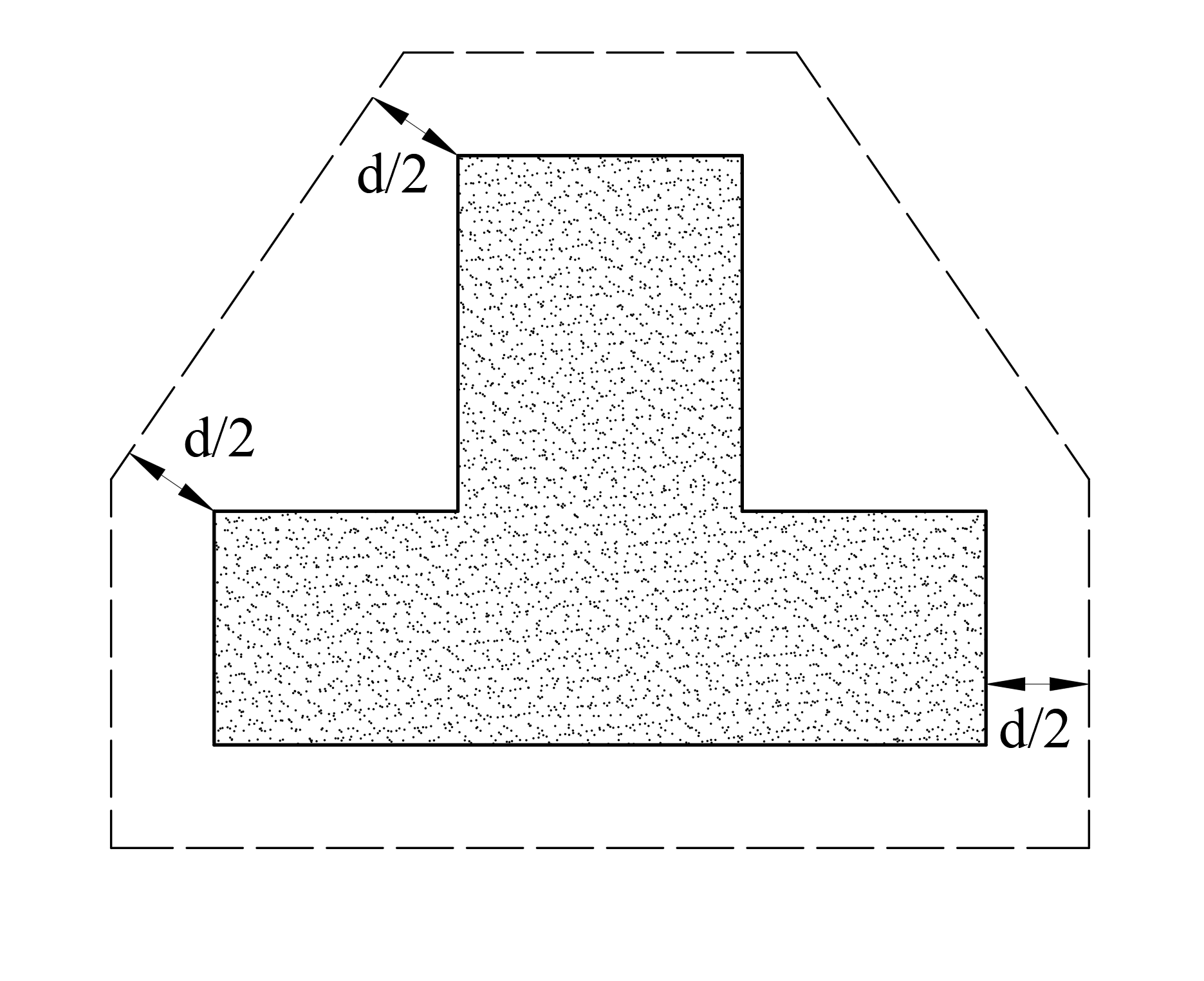
In polygon columns, the punching circumference (u p ) is taken into account as shown in the example picture below by creating a suitable geometric shape by drawing tangents at a distance d / 2 from the column surface and corners in accordance with TS500 Section 8.3.1 .
TS500 Section 8.3.1If there is more than one critical section, it is stated that the punching calculation should be made separately for each section. For this reason, when the floor head is defined at the end of the column, there are two separate punching circumference for the column in question and two separate punching calculations are made. In the first case, the punching strength is checked according to the punching circumference calculated at d / 2 distance from the column edges. However, here the slab useful height (d) is obtained by subtracting the cover from the sum of slab thickness and header thickness. In the second case, the punching strength control calculated at a distance of d / 2 from the head edge is checked. In this step, the slab useful height (d) is obtained by subtracting the cover from the slab thickness.
Stapling area after calculating the punching circumference, A z be calculated.
A z : Stapling area. It is obtained by multiplying the punch perimeter by the slab useful height, d.
A z = u p xd
d: refers to the useful height of the floor. It is the value obtained by subtracting the floor cover from the thickness of the floor.
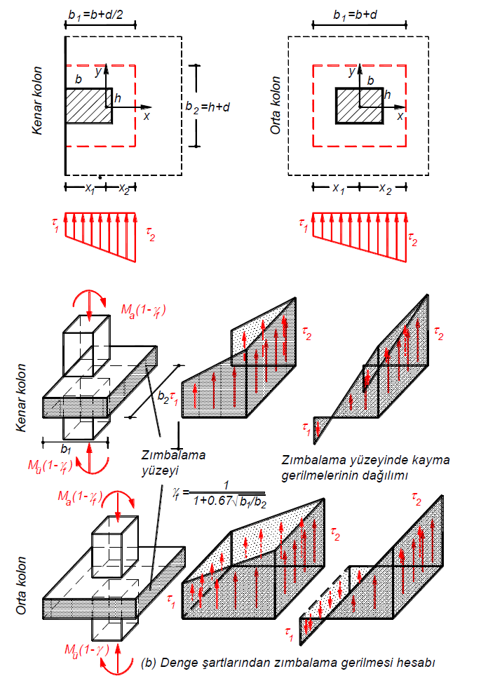
Without girders plaques in the laying-column connection system, vertically together with the withstand Redundancy Factor D with increased with earthquake floor level to the column under the influence Taking into consideration the direction γ of the total bending moment transmission for the bending property value obtained by increasing the coefficient 1-γ f for increasing the coefficient The value obtained is assumed to be transferred through punching (shear) stresses.
γ: It is the coefficient reflecting the bending effect in the punching calculation. According to Section 7.11.9 of TBDY , it is accepted that the value obtained by multiplying the total bending moment transferred from the column in the direction of the earthquake by the coefficient γ with the bending reinforcement and the value obtained by multiplying the coefficient γ v ( v = 1-γ) is assumed to be transferred by punching stresses. . The coefficient is calculated as shown in TBDY Equation 7.28 .
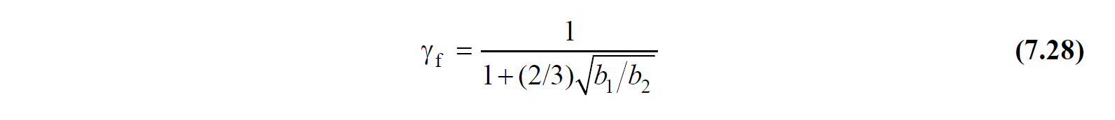
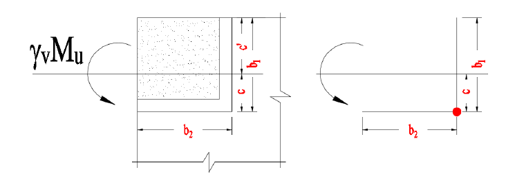
Here, the dimensions of the rectangular punching circumference are b 1 (in the loading direction) and b 2 (in the direction perpendicular to the load). The picture below shows an example for a corner column.
The coefficient is calculated in both axes (major and minor axes) of the punching circumference according to the loading direction.
In this case , the bending moment values (DM d (maj) , DM d (min) ) calculated by considering the Strength Reduction Coefficient D while calculating the punching stresses (τ pd, 1 , τ pd, 2 ) and the coefficient (γ v = 1-γ) multiplied.
c (maj) , c (min) : The centers of gravity calculated in the direction of the moment around the strong and weak axis of the punching area. As shown in the figure below, c (maj) , c (min) values vary in the moment direction .
c ' (maj) , c' (min) : The center of gravity of the punching field calculated in the opposite direction of the moment around the strong and weak axis. As shown in the figure below, c ' (maj) , c' (min) values vary according to the moment direction .
V d : It is the design shear force value based on the punching calculation. It is calculated as the difference of axial pressure forces calculated under the combined effect of vertical loads and earthquake loads occurring in the regions above and below the slab level in columns or walls.
M d (maj) , M d (min) : It is the design moment calculated under the combined effect of gravity and earthquake loads in the strong and weak axis of the column and is the basis for the slab punching calculation. While calculating the punching stresses (τ pd, 1 and τ pd, 2 ), the bending moment values (M d (maj) , M d (min) ) occurring under the combined effect of earthquake loads calculated by taking into account the gravity loads and the Extra Strength Coefficient D are used. The stress distribution is determined according to the direction of these moments.
J (maj) , J (min) : It is the sum of the polar inertia and second moments around the strong and weak axes of the surfaces forming the punching area (A z ). J value is calculated by considering the strong axis and weak axis separately.
Calculation of J values for a single direction in a sample rectangular column is done as follows. J value is calculated separately on both the strong axis and the weak axis.
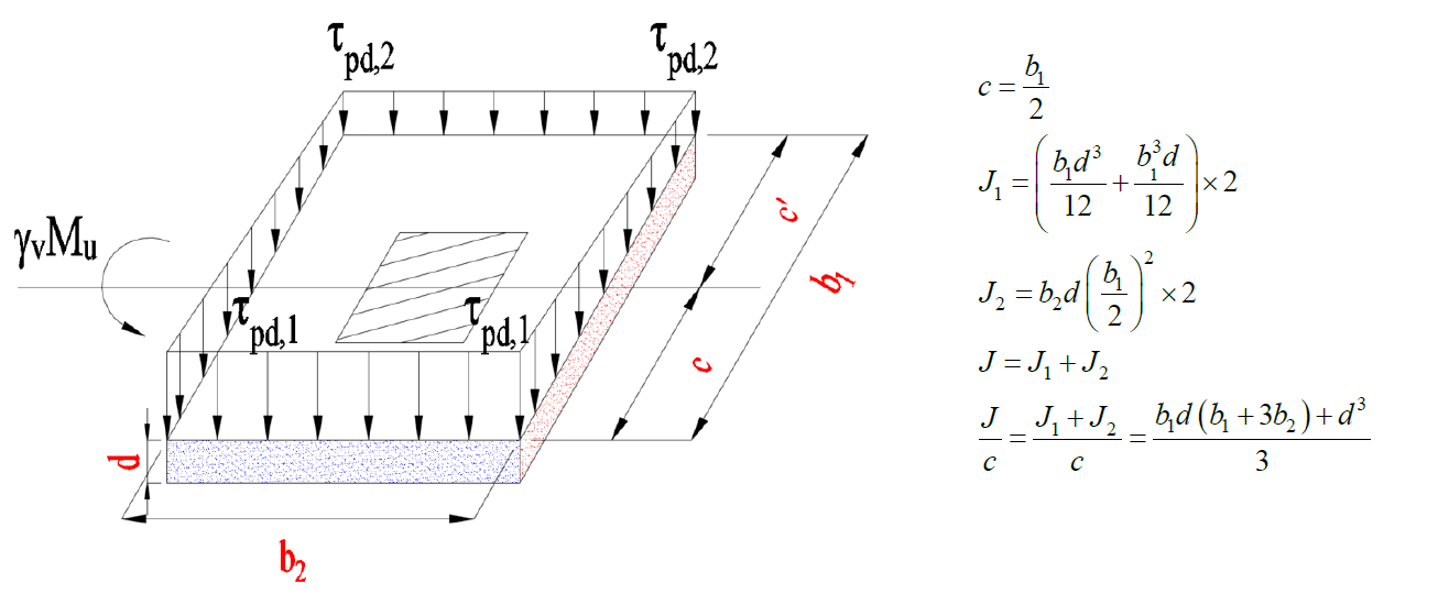
J 1 : It shows the polar moment of inertia of the punching area (red shaded area) perpendicular to the axis in the figure above.
J 2 : The above figure shows the second (inertia) moment of the punching area (blue shaded area) parallel to the axis with respect to the axis.
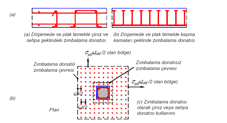
Use of Stapling Reinforcement
According to Article 7.11.10 of TBDY , in cases whereτ pd ≤ f ctd condition is not fulfilled and plate thickness is greater than 250 mm, punching strength can be increased by using punching equipment.
The punching strength of the reinforcement slab is at most 1.5f ctd , considering the equation specified in TBDY Equation 7.29a , when uniformly spaced wedge or stand reinforcements are used as punching reinforcement .
When shear wedges are used as punching equipment, the punching strength of the reinforcement plate is at most 1.75f ctd considering the equation specified in TBDY Equation 7.29b .
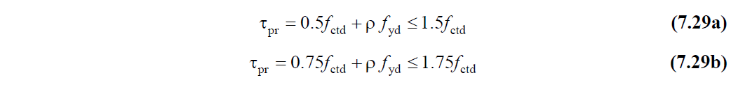
ρ: Cross-sectional area of punching reinforcement per unit area
f yd : Design yield strength of punching reinforcement
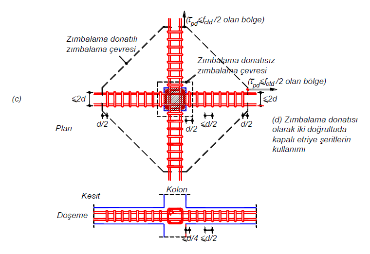
In cases where closed stirrup strips in two perpendicular directions are used as punching equipment , the punching strength is at most 1.5f ctd according to TBDY Equation 7.30a .
In cases where two vertical sliding wedge rails are used as punching equipment, the maximum punching strength is 1.75f ctd according to TBDY Equation 7.30b .
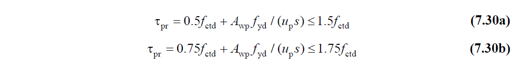
A wp : The total cross-sectional area of the vertical punching rebars on the punching perimeter.
By using punching equipment, the punching strength can be increased up to 1.5f ctd or 1.75f ctd as stated above .