
|
Open the Structural Analytical Model file with the optimized structural and examine the results by using Analysis+Design command. |
-
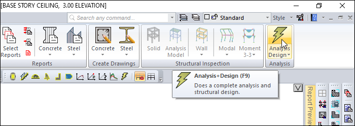
Click the Analysis+Design (F9) command.
-
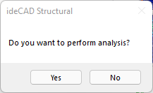
Do you want to perform analysis? question will be asked. Click the Yes button.
-
Wait for the analysis to complete in the ideCAD Structural Analysis Status window.
-
After the analysis is complete, click OK buton to close the window.
-
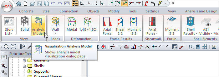
Click Structural Inspection in the ribbon menu.
-
From the View heading, click the Analysis Model command.
-
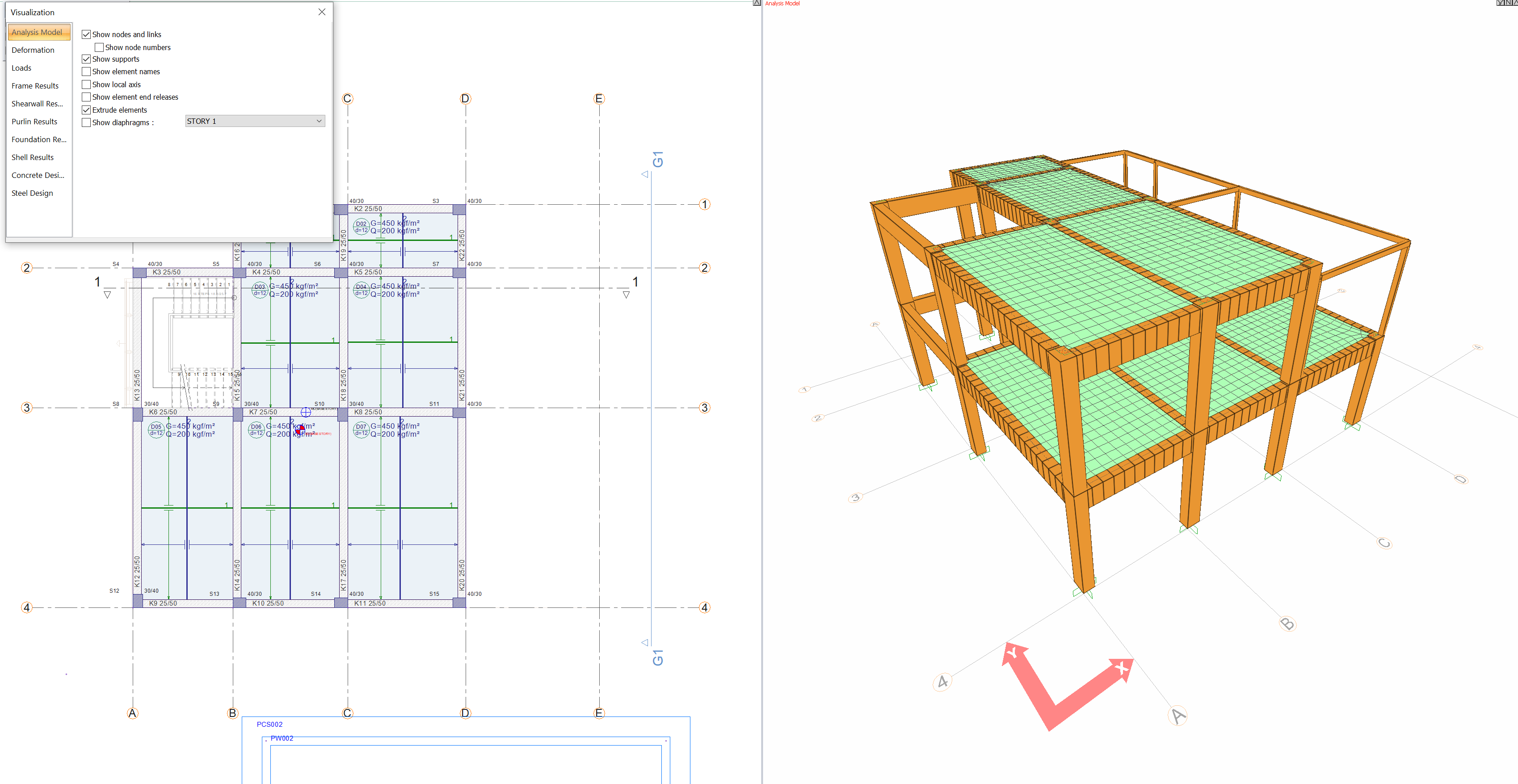
Rod and shell finite element analysis model is created automatically.
-
From the Ribbon Menu, Deformation heading, click on the 1.4G+1.6Q command.
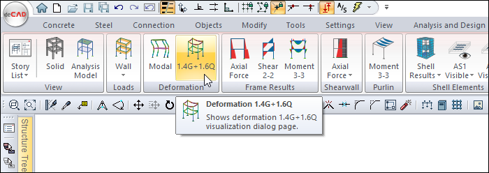
-
Case/combination and animation occurs for 1.4G+1.6Q in the Visualization Window.
-
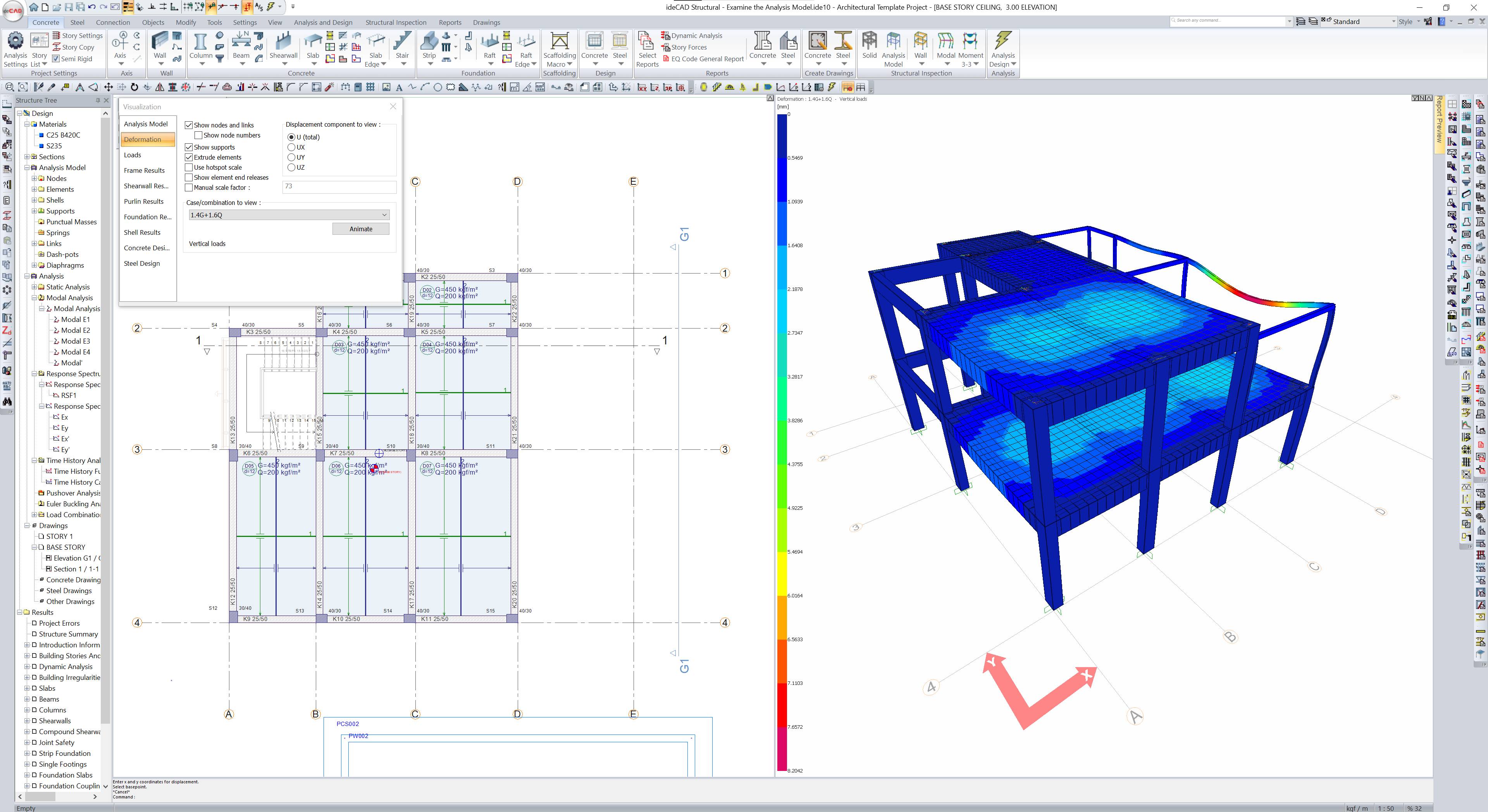
Click Visualization Dialog , Deformation tab, Case/combination list.
-
Select Modal E1.
-
Mod Shapes are created in the Visualization Window .
-
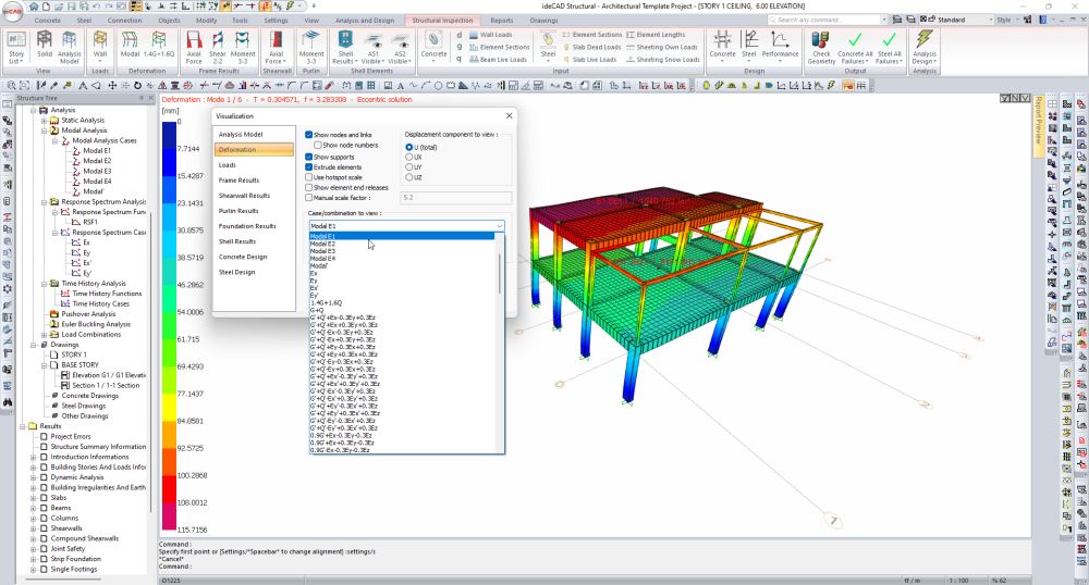
From the Visualization Dialog, click the Animate command.
-
An animation of Mod Shapes occurs in the Visualization Window .
-
From the Visualization Dialog , click the Stop command to stop the animation.
-
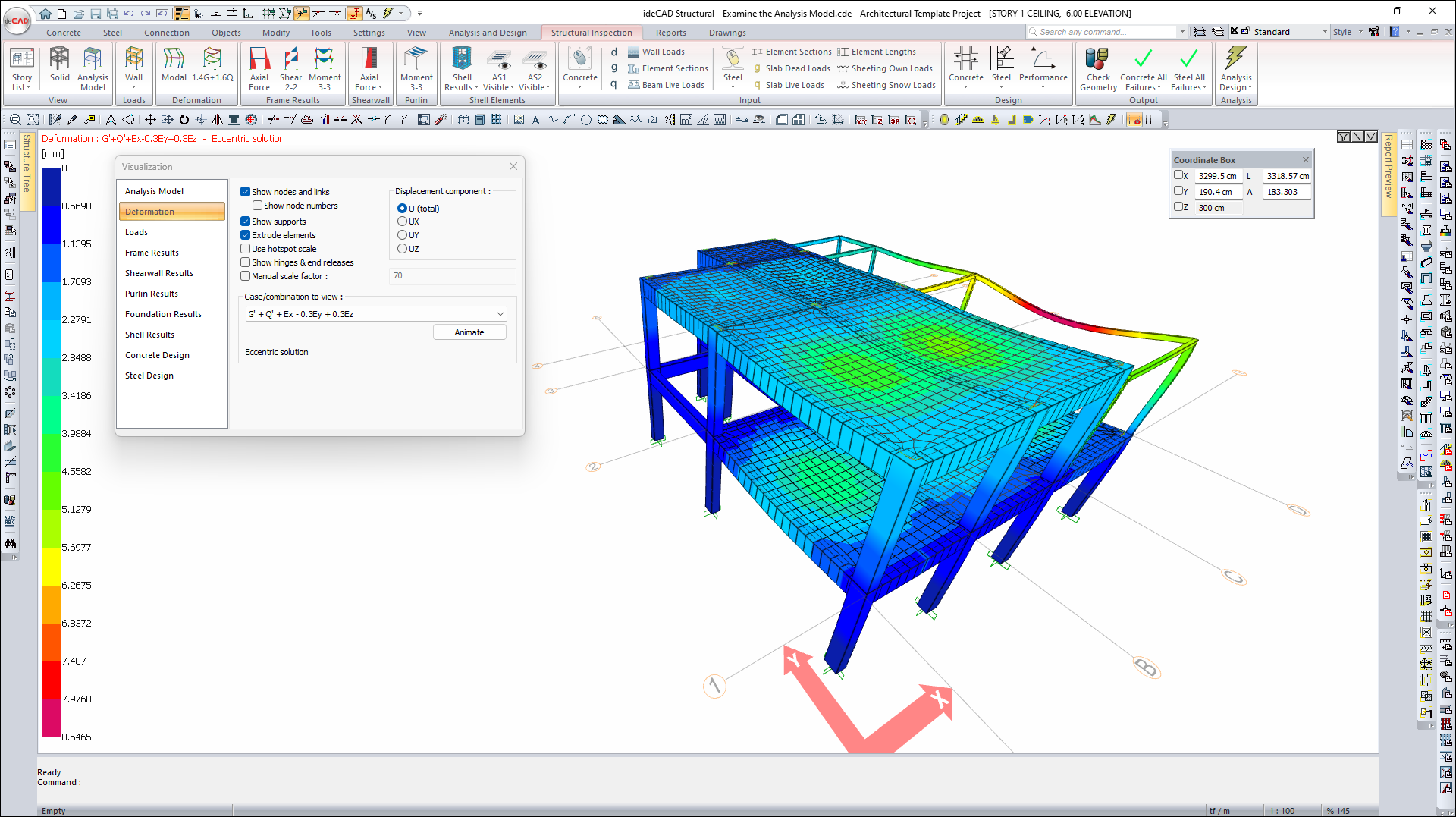
Click the Visualization Dialog, Deformation tab, Case/combination list.
-
Choose the combination G'+Q'+Ex-0.3Ey+0.3Ez.
-
Deformations occur in the Visualization Window.
-
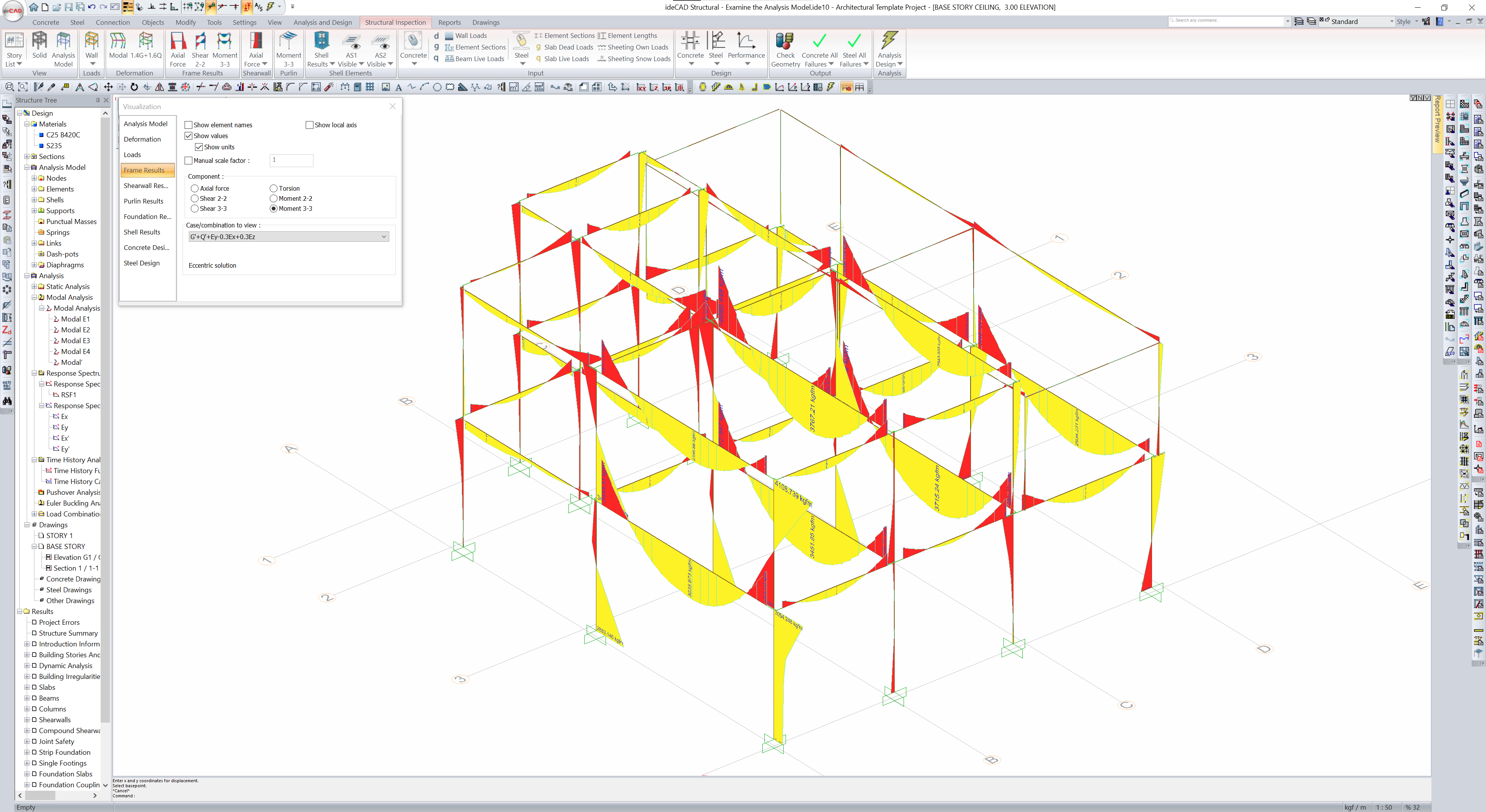
From the Ribbon Menu, Frame Results heading, click on the Moment 3-3 command.
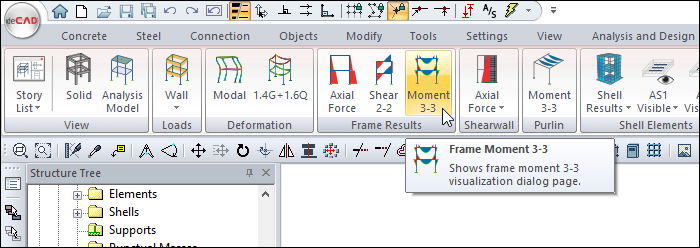
-
The Moment Diagram is created in the Visualization Window
-
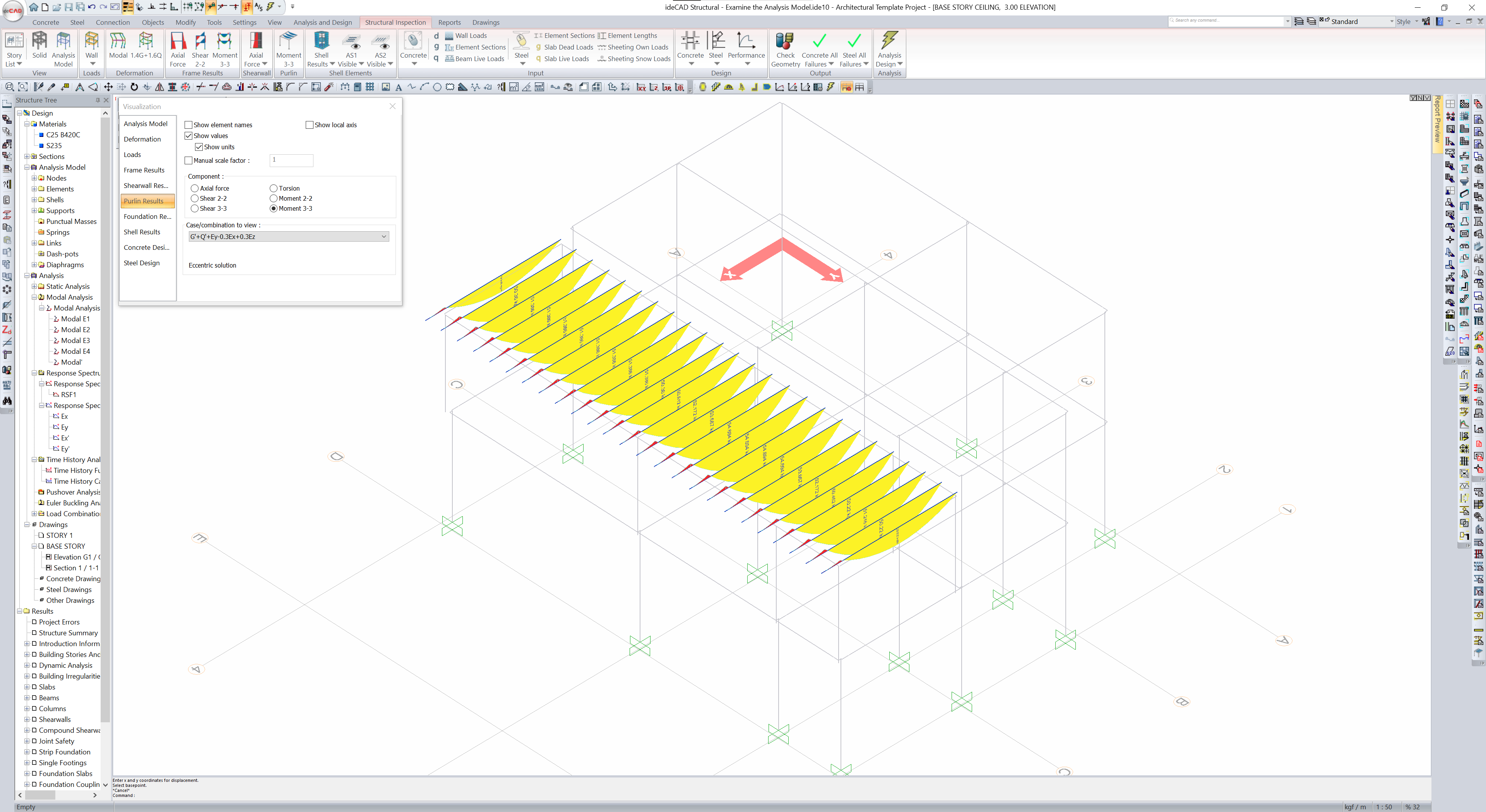
From the Ribbon Menu, Purlin heading, click on the Moment 3-3 command.
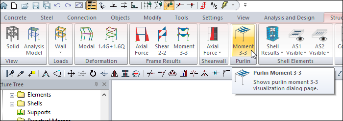
-
Moment Diagrams of purlins are created in the Visualization Window .
-
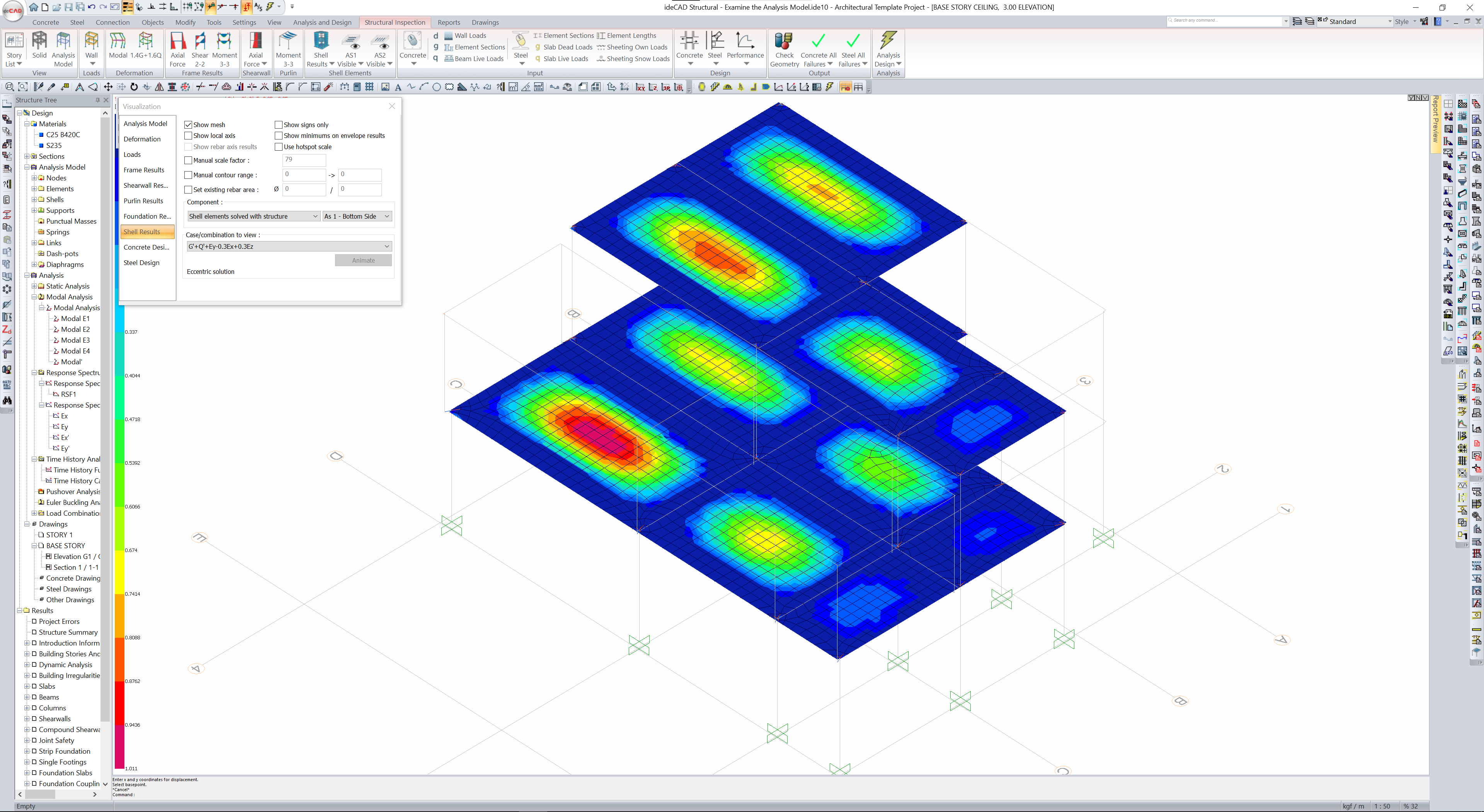
From the Ribbon Menu, Shell Elements heading, click on the Shell Results .
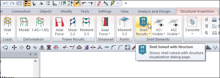
-
On the Visualization Dialog, Shell Results tab, click on the Component list.
-
Select the Slab Results and M11.
-
Select 1.4G+1.6Q from the Case/combination list.
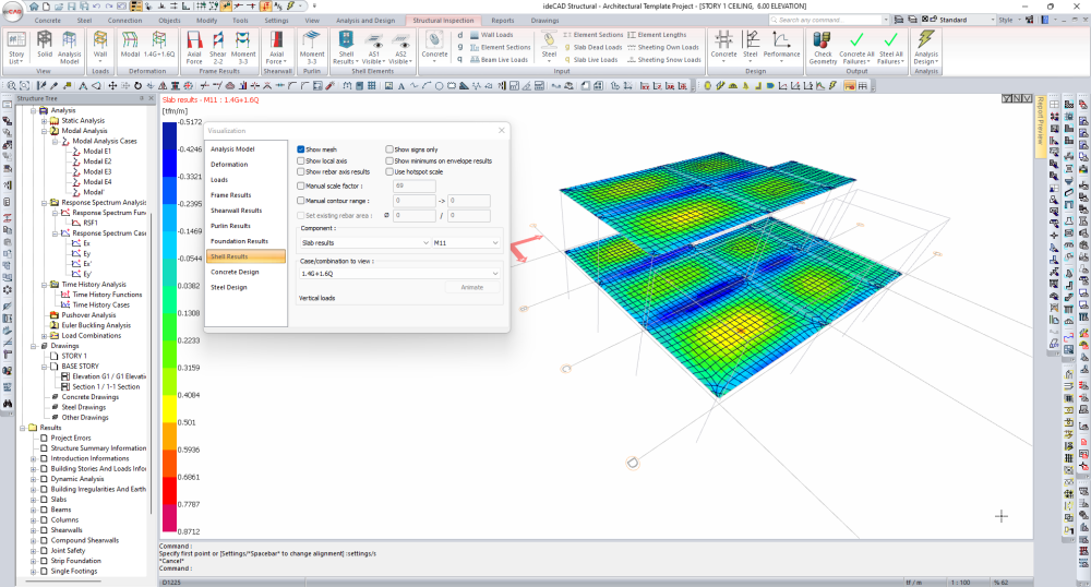
-
In the Visualization Window, finite element stresses will be occur.
-
From the Ribbon Menu , Shell Elements heading, open the As1 visible list.
-
Click the AS1 Under command.
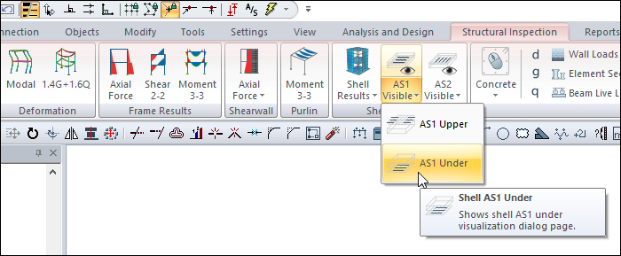
-
In the Visualization Window, the required reinforcement area values of the shell elements are created.
-
Open the Concrete All Failures list from the Ribbon Menu, Output heading.
-
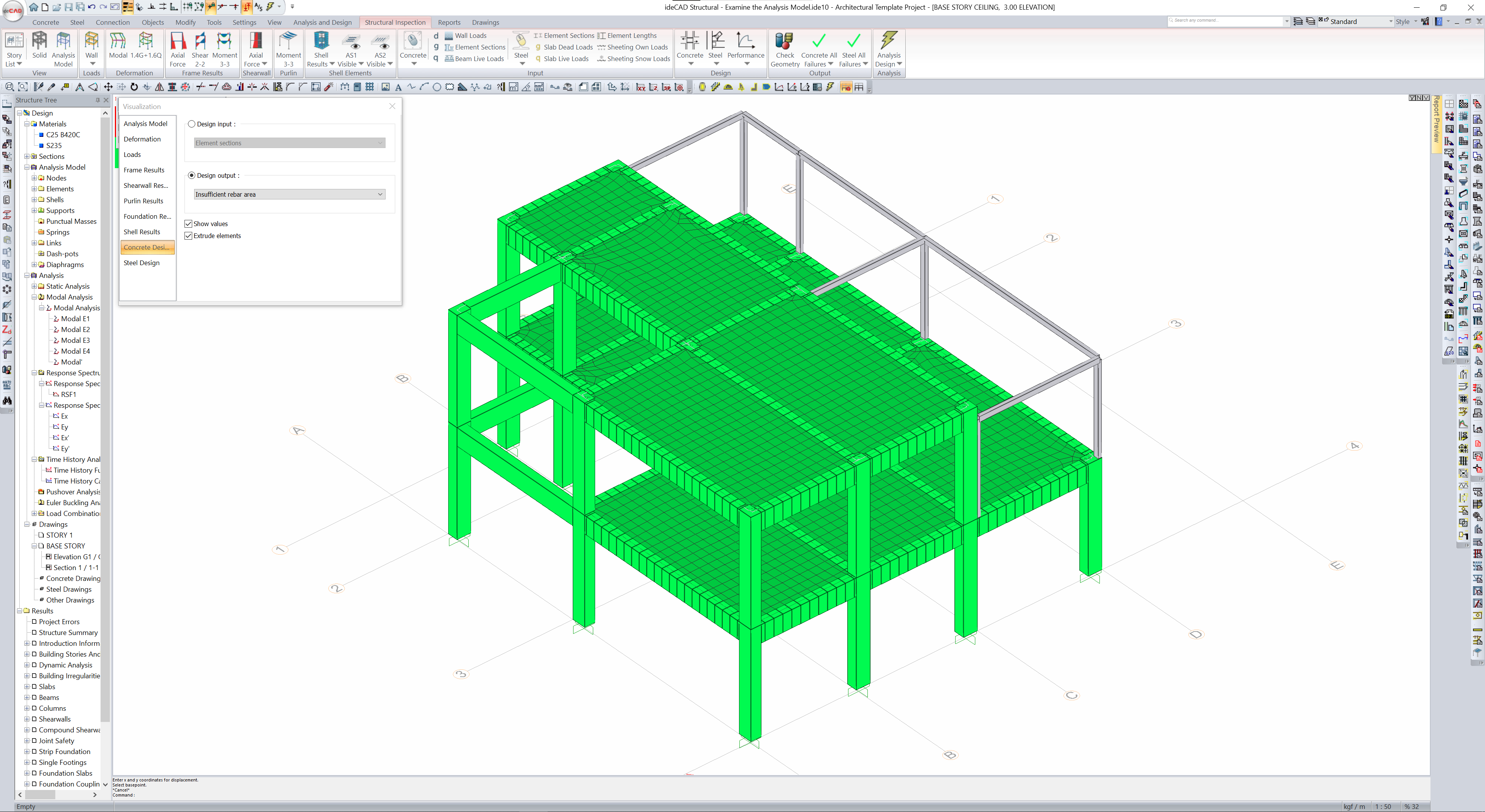
Click the Concrete Insufficient Rebar Area command.
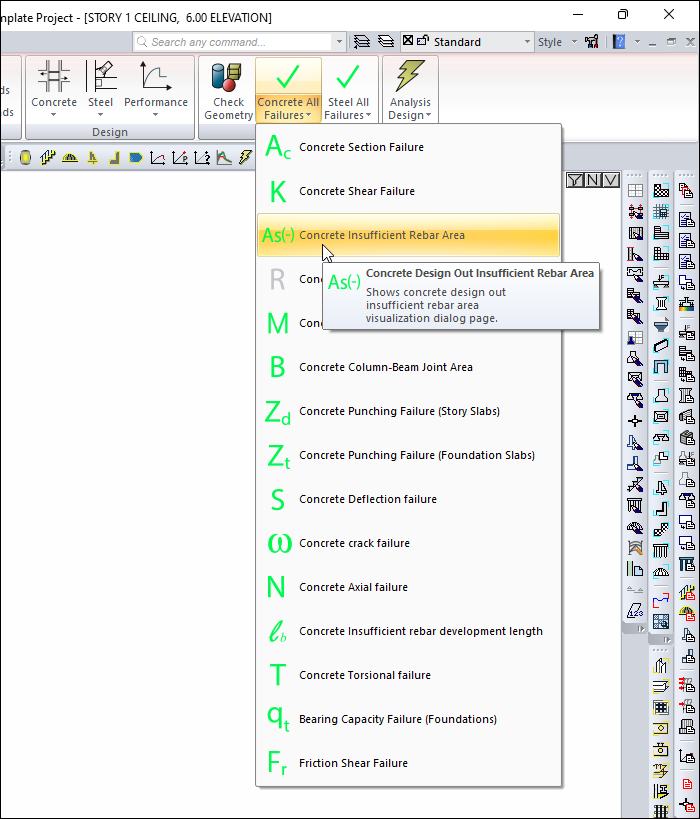
-
The results of the insufficiency occur in the Visualization Window .
-
It means that there is no insufficiency in the green colored elements, and there is an insufficiency in the red colored elements.
Follow the steps of the video below.
Next Tutorial