
In this example, independent hand calculation results of the internal force values obtained as a result of the earthquake calculation with the mode shapes, periods and mode combination method of a two-storey system with a single span are made and the results of ideCAD Structural are compared. The damping ratio used in response spectrum analysis is taken into account as 5%. Full Quadratic Combination (TKB or CQC) has been used as the modal combination method . Independent hand calculation solutions of periods, horizontal displacements and bending moments calculated as a result of modal analysis were made according to Chopra 2012.
Important Note: In this system solution, only bending deformations are taken into consideration, elongation and shear deformations are ignored in terms of ease of manual solution. The cross-sectional area is multiplied by 10000 to neglect the elongation deformations, and the shear areas are defined as zero "0" to neglect the shear deformations.
Important Note: Only UX, UZ and RY degrees of freedom are used in the system to facilitate independent manual calculation. Since the manual solution is two-dimensional, fixed supports are defined at the joints in the direction of UY. Therefore, mode shapes and periods occur only on the X axis. In ideCAD Static, dynamic analysis is made by considering three-dimensional masses and all degrees of freedom.
Important Note: The masses are defined only on the beam members for ease of independent manual calculation.
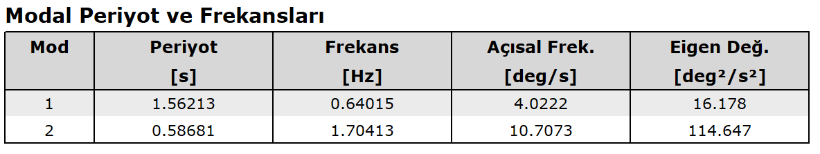
Comparison of periods
|
Compared Value |
ideCAD Structural |
Manual solution |
Percentage of error |
|---|---|---|---|
|
1st Mode Period |
1.562 |
1.562 |
0% |
|
2nd Mode Period |
0.5868 |
0.5868 |
0% |
Comparison of response displacement results
|
Node and direction |
ideCAD Structural |
Manual solution |
Percentage of error |
|---|---|---|---|
|
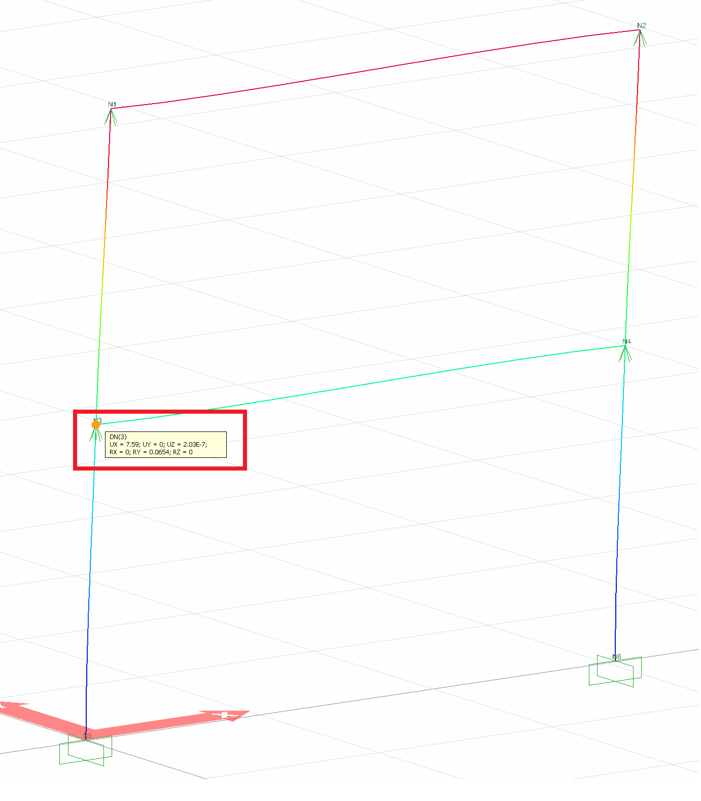
3 DN (UX) |
7.59 |
7.59 |
0% |
|
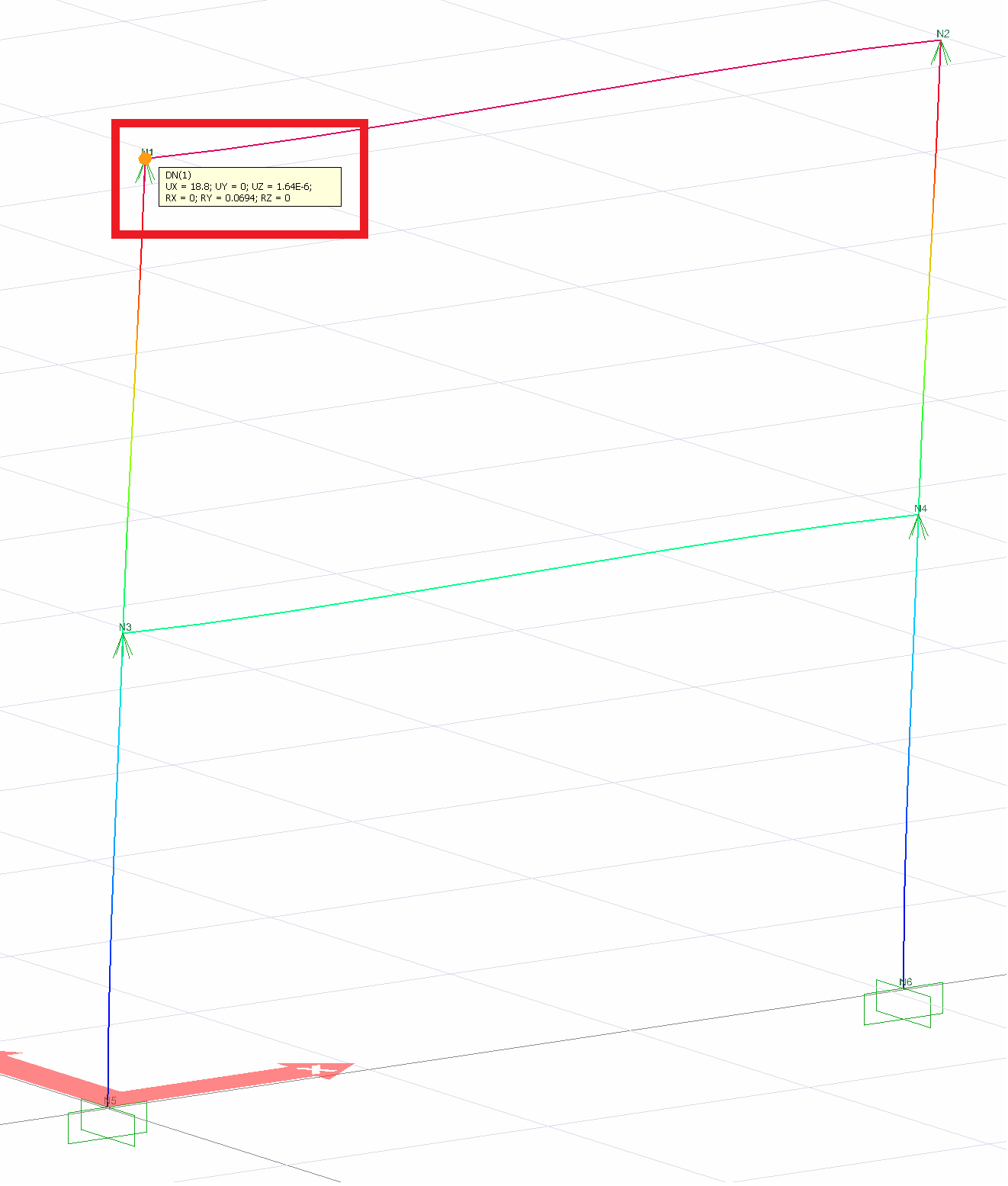
1 DN (UX) |
18.8 |
18.8 |
0% |
Element end moments comparison (M 33 ) kip-ft
|
Workman |
Node |
ideCAD Structural |
Manual solution |
Percentage of error |
|---|---|---|---|---|
|
|
3 |
817.99 |
817.99 |
0% |
|
4 |
817.99 |
817.99 |
0% |
|
|
|
one |
433.81 |
433.81 |
0% |
|
2nd |
433.81 |
433.81 |
0% |
|
|
|
3 |
568.47 |
568.47 |
0% |
|
5 |
1056.17 |
1056.17 |
0% |
|
|
|
one |
433.81 |
433.81 |
0% |
|
3 |
499.81 |
499.81 |
0% |
Geometric Properties and System Description
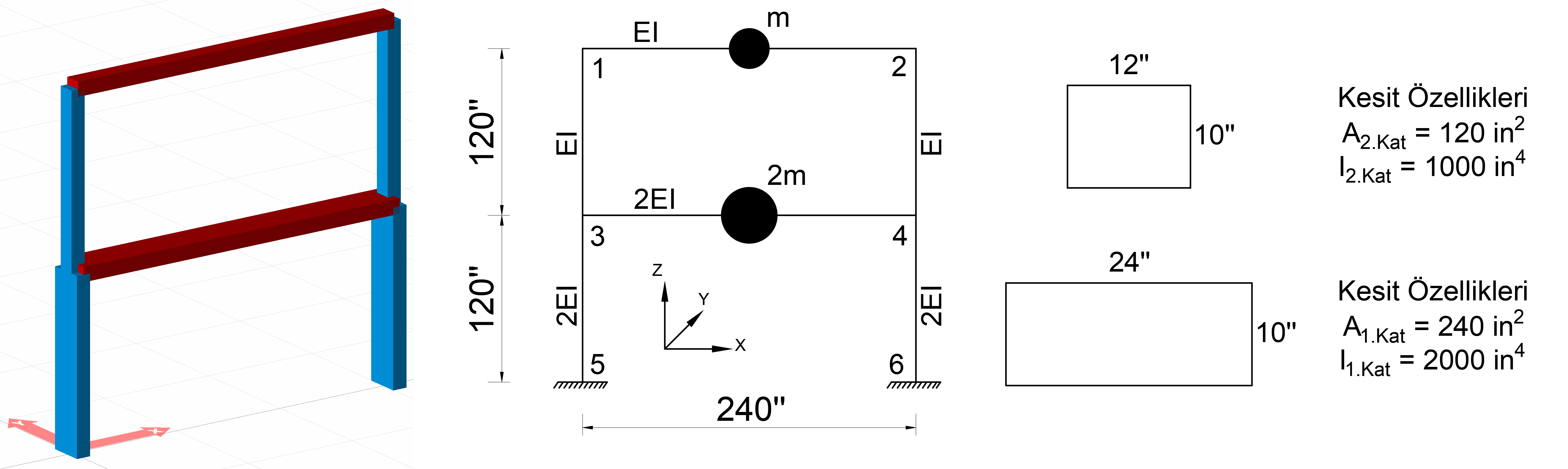
In the above image, a 2-storey system with 1 opening is defined. Each floor height is defined as 120 inches and span is 240 inches. The freedoms of the node points are in the direction of UX, UY and RZ and the masses are defined only to the elements between 1-2 and 3-4 joints.
The first floor frame members (the elements indicated by 2EI) are 24 '' (24 inch) wide and 10 '' high rectangular sections. The geometric properties of the first floor frame elements are calculated as follows.
The area of the first floor element 1.Floor = 24 * 10 = 240 in the second
first floor elements inertia I 1st Floor = 2 = (1.12) * (24 * 10 3 ) = 2000 in the fourth
calculated as.
The second floor rod members (the elements indicated by EI) consist of rectangular sections 12 '' wide and 10 '' high. The geometric properties of the first floor frame elements are calculated as follows.
The area of the second floor element 2.Kat = 12 * 10 = 120 in the second
second moment of inertia of the floor elements I 2.Kat = I = (1/12) * (12 * 10 3 ) = 1000 in the fourth
calculated as.
The modulus of elasticity of the material used was taken into account as E = 3000 k / in 2 and the
mass value as m = 0.5182 kip-sec 2 / in
.
The ratio of moments of inertia will be used when defining member bending stiffness. In this case, (2EI) values are used for the bending stiffness of the first layer elements and (EI) values for the second layer elements. Here, E = 3000 k / in 2 and I = 1000 in 4 .
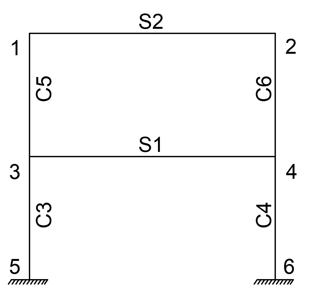
Element names and joint numbers are shown in the image below.
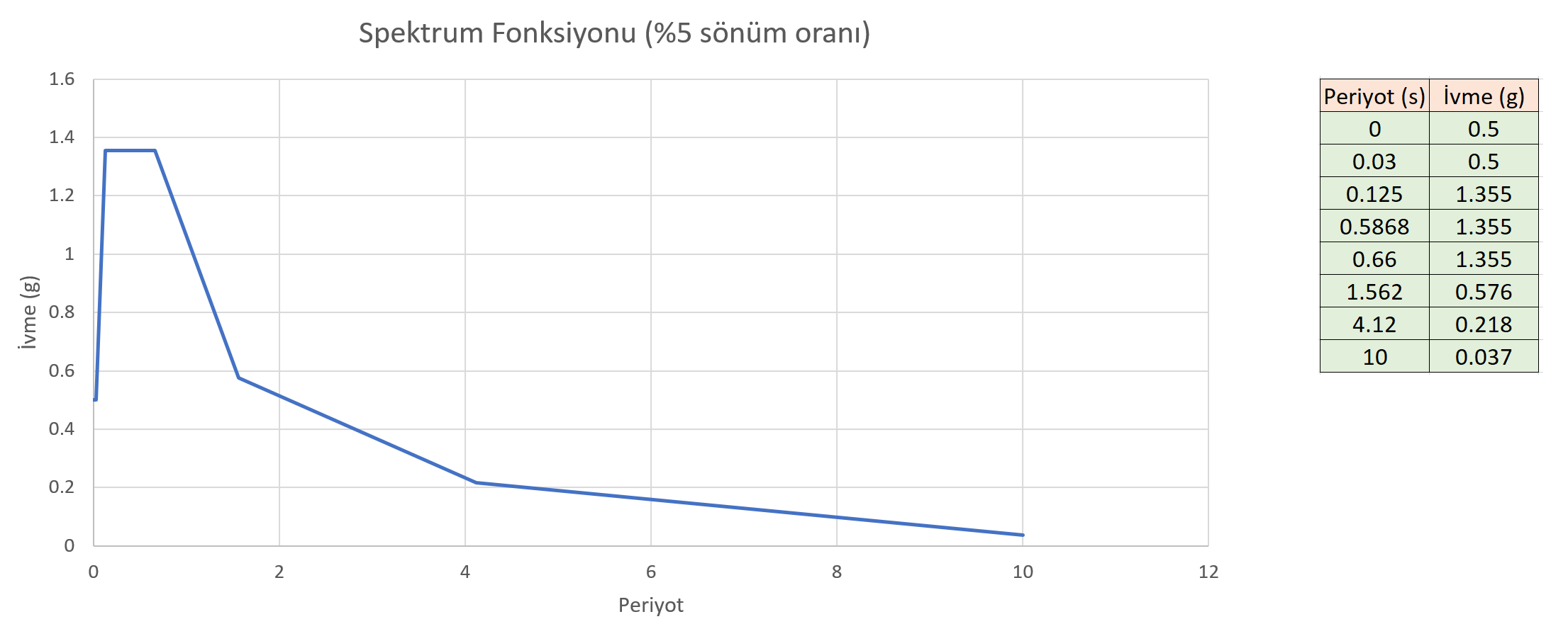
In the Mode Joining Method used , the damping rate is taken into account as 5%. The horizontal elastic design spectrum (Response spectrum function) is defined as follows.
You can reach the ID file with defined sections and horizontal elastic design spectrum below.
Mod Birleştirme Yöntemi (Response Spektrum Analizi).rar
Mode Combining Method
The first step is to obtain mass and stiffness matrices while performing modal combination analysis of the two-storey sample system. The following procedure is followed while obtaining the stiffness matrix.
There are 6 nodes in the system below. Joints 5 and 6 of these joints are connected with the built-in support. Since the strain deformations in the system are also neglected, each joint point can move in the UX direction and the RZ direction. Since the strain deformations are neglected, joints 1-2 and joints 3-4 will make the same change in the UX direction. Considering these conditions, there are 6 freedoms in total. For this reason, the total stiffness matrix of the structure is found in 6x6 dimensions.
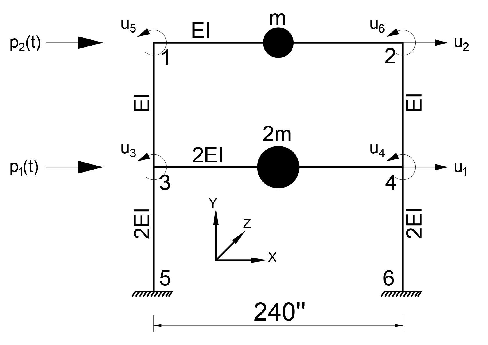
However, in this system, it is accepted that the masses can only move in the UX direction. Therefore, the mass matrix must be 2x2 in size. Mass matrix and stiffness matrices must have the same dimensions in order to perform modal analysis. For this reason, the stiffness matrix, which is 6x6 in terms of ease of calculation, will be reduced to 2x2 and the horizontal voiding stiffness matrix will be formed.
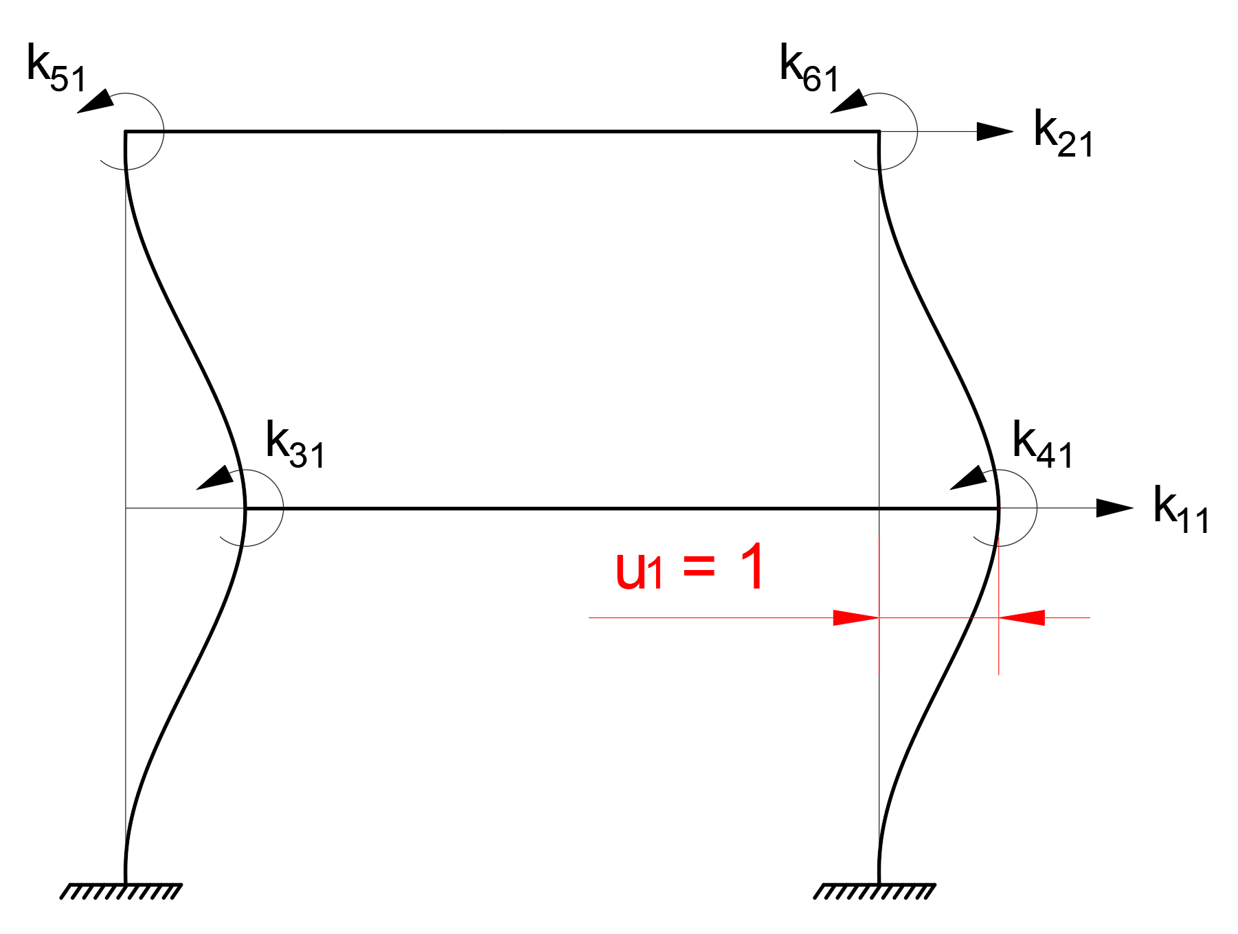
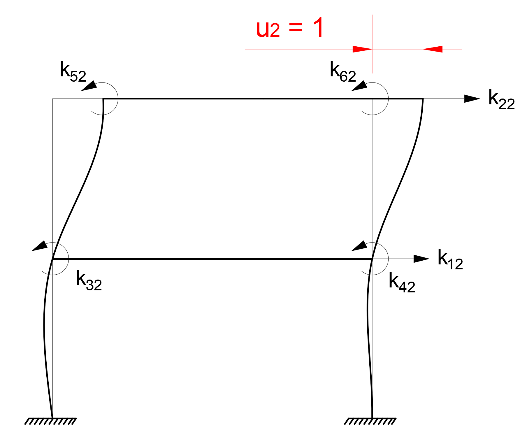
While creating the stiffness matrix, the forces that occur when each freedom changes a unit can be used. In this case , the forces generated by a unit deformation for each freedom (u 1 , u 2 , u 3 , u 4 , u 5 , u 6 ) are the elements of the stiffness matrices.
Note: In the k mn term, the index m indicates the stiffness term at the node, and the index n is the node that changes the unit. For example , row 1 of the stiffness matrix k 12 is placed in column 2 and is the stiffness at joints 2 due to the loading u 2 = 1.
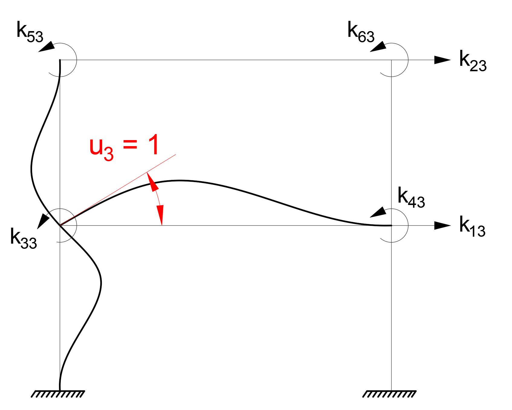
The following figures show the unit deformations and the resulting stiffness matrix terms for u 1 , u 2 , u 3 freedoms. Similar operations are applied for u 4 , u 5 , u 6 .
The stiffness matrix, which consists of translation (u 1 , u 2 ) and rotation (u 3 , u 4 , u 5 , u 6 ) freedoms at the node points , can be divided into 4 parts. The names of these sections can be made as follows.
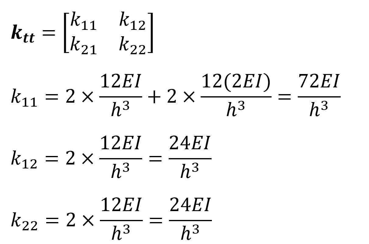
k tt : It is the translational stiffness matrix formed due to unit loading (u 1 = 1 and u 2 = 1) to the translational freedom .
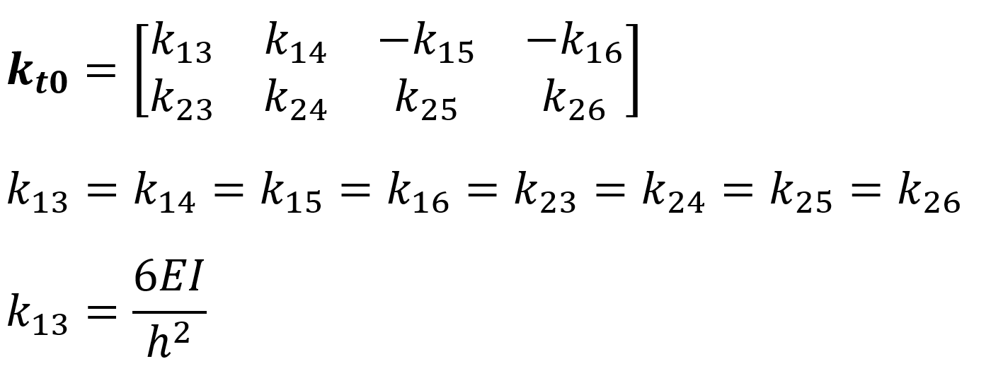
k t0 : It is the translational stiffness matrix caused by the unit loading of the rotational freedom.
k t0 : It is the rotational stiffness matrix formed due to the unit loading of the translational freedom.
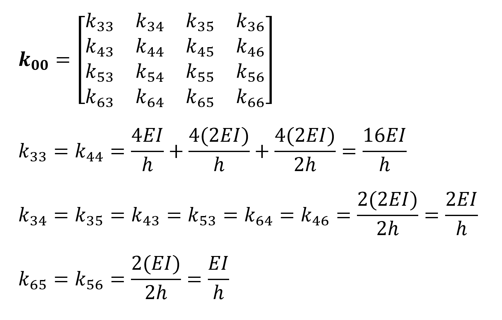
k00 : It is the rotational stiffness matrix formed due to the unit loading of the rotational freedom.
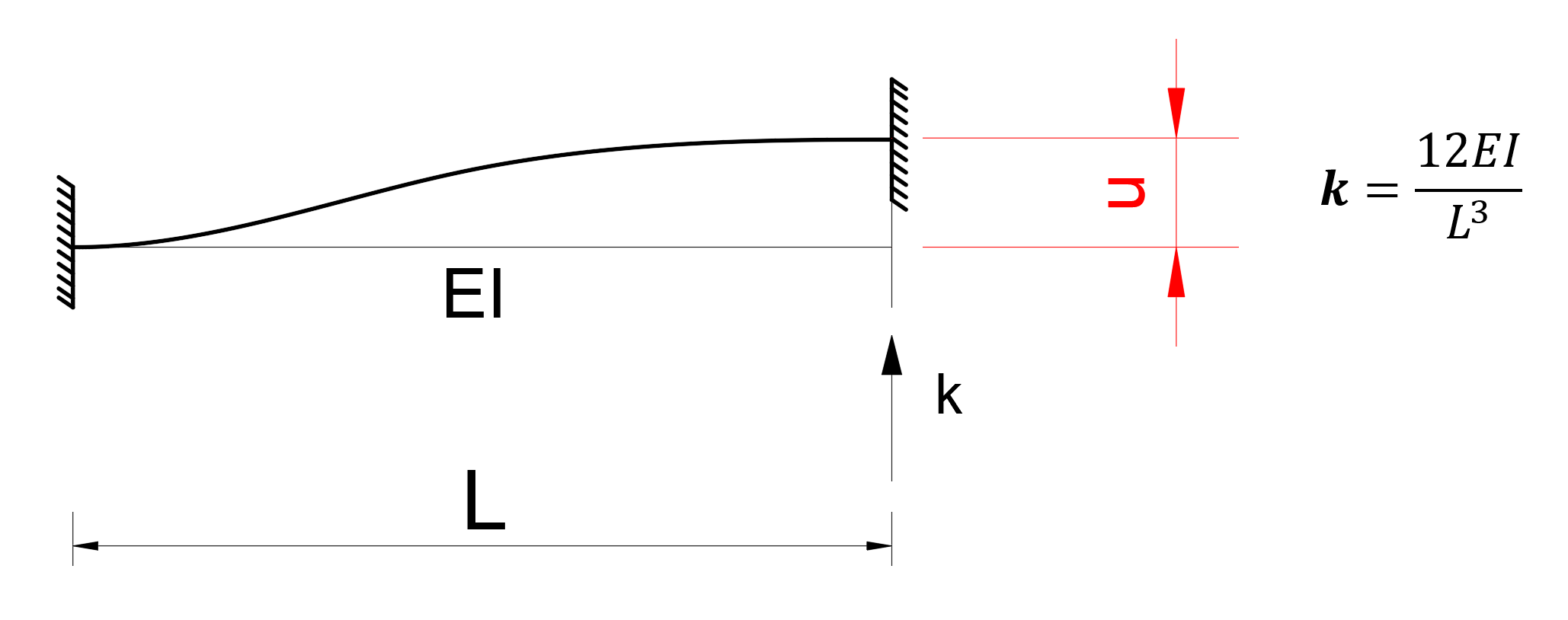
The translational stiffness value of an element with both ends of it is given below. In the figure below, the force required for u = 1 unit of translation is expressed as 12EI / L 3 .
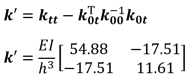
To find the k tt matrix , the horizontal displacement stiffnesses of u 1 = 1 and u 2 = 1 unit loadings are calculated as follows.
In order to find the matrix k t0 = (k 0t ) T, the stiffness of joints consisting of the unit loadings u 1 = 1 and u 2 = 1 is calculated as follows.
To find the k 00 matrix , the horizontal displacement stiffnesses consisting of u 3 = 1, u 4 = 1, u 5 = 1 and u 6 = 1 unit loadings are calculated as follows.
The total stiffness matrix, k , can be written by putting all these matrices together as follows.
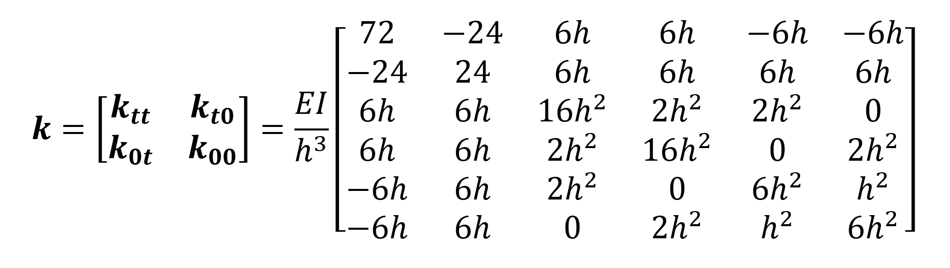
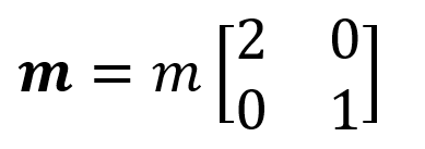
As can be seen, the stiffness matrix, k , was obtained in 6x6 format. However, since it is assumed that the masses can only move in the UX direction, the mass matrix can be written as 2x2. In this case, the matrix k can also be reduced to 2x2 format.
The mass matrix is written in 2x2 format as follows.
After writing the mass matrix m and the stiffness matrix k ' corresponding to the motion of these masses, the determinant of the frequency equation is equal to zero, and the modal shapes and the natural vibration period of each mode can be found with the solution of eigen vectors.
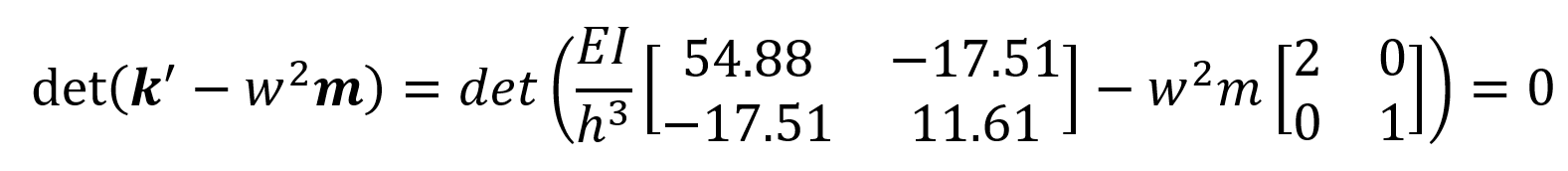
From the solution of det ( k ' -w 2 m ) = 0 there are two solutions w. These refer to the angular vibration fractions of each mode. In the above equation w n means the angular frequency of the n th mode.
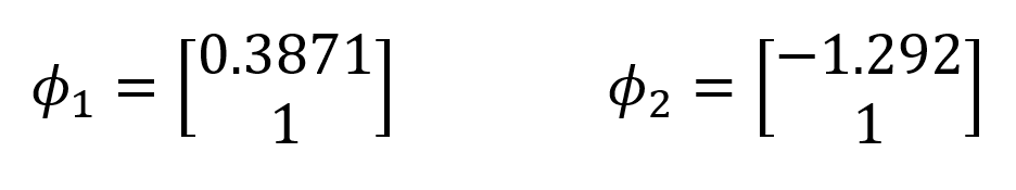
After w 1 and w 2 values are found, the 1st mode shape şekli 1 and 2nd mode shape ϕ 2, which are the modal shapes according to u 1 and u 2 freedoms, can be found.

The mode shapes ϕ 1 and mod 2 appear as 2x1 matrices. However, due to the nature of the Eigen vector solution, the equation det ( k ' -w 2 m ) = 0 is a first-order linear dependent equation. Therefore, mode vectors can be expressed as ratios of each other. One element of the mode vectors is given the unit value 1 and the other element is found. In this way, the ratio of mode shapes to each other is determined.
E = 3000 k / in 2 ,
m = 0.5182 kip-sec 2 / in,
I = 1000 in 4 and
h = 120 in
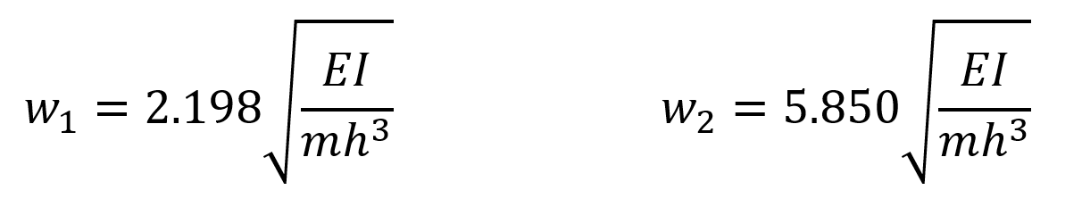
are given in the system information. When these values are substituted in the equations w 1 and w 2 ,
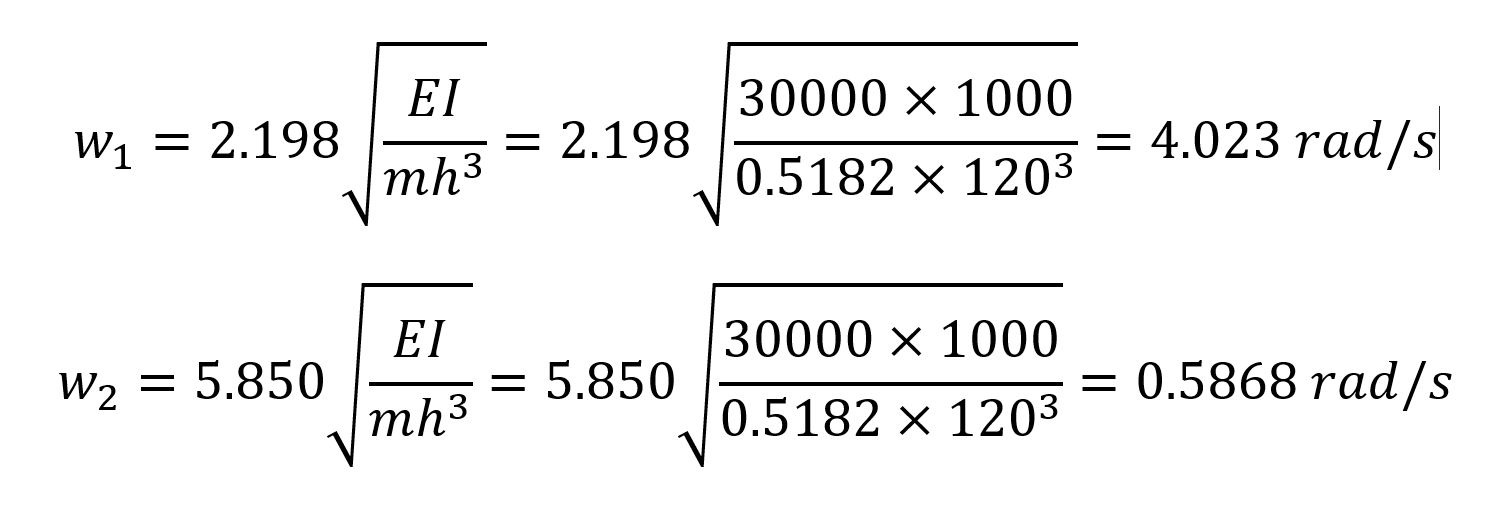
angular frequency values are found. After finding the angular frequencies, the natural vibration periods of each mode can be found.
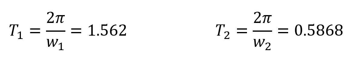
T 1 = 1.562 s and T 2 = 0.5868 natural vibration periods results were found to be exactly the same with ideCAD Structural.
After finding the mode shapes and natural vibration periods, the nodal deformation values for each mode must be found.
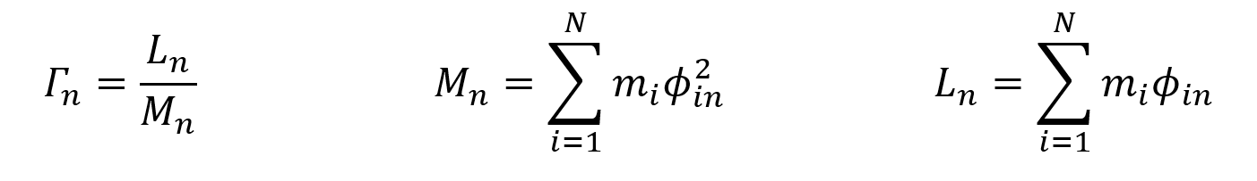
In this case, for any nth mode, the modal contribution factor, generalized modal mass and effective modal mass are found as follows, respectively.
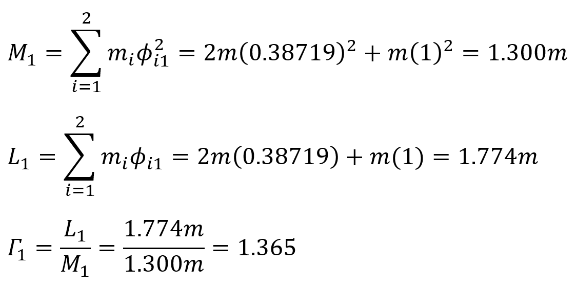
When these formulas are adapted for the first mode,
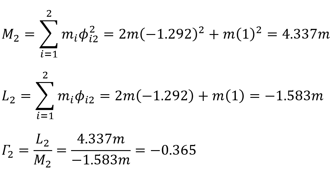
for the second mode,
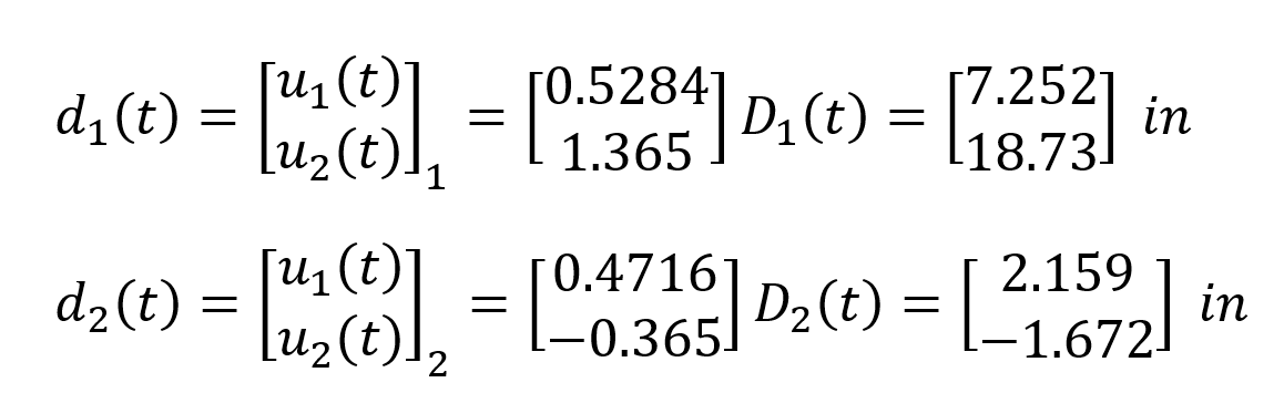
values are found. Using these values, the deformation vectors d 1 (t) and d 2 (t) for the first and second mode are found as follows.
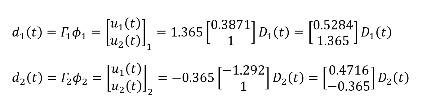
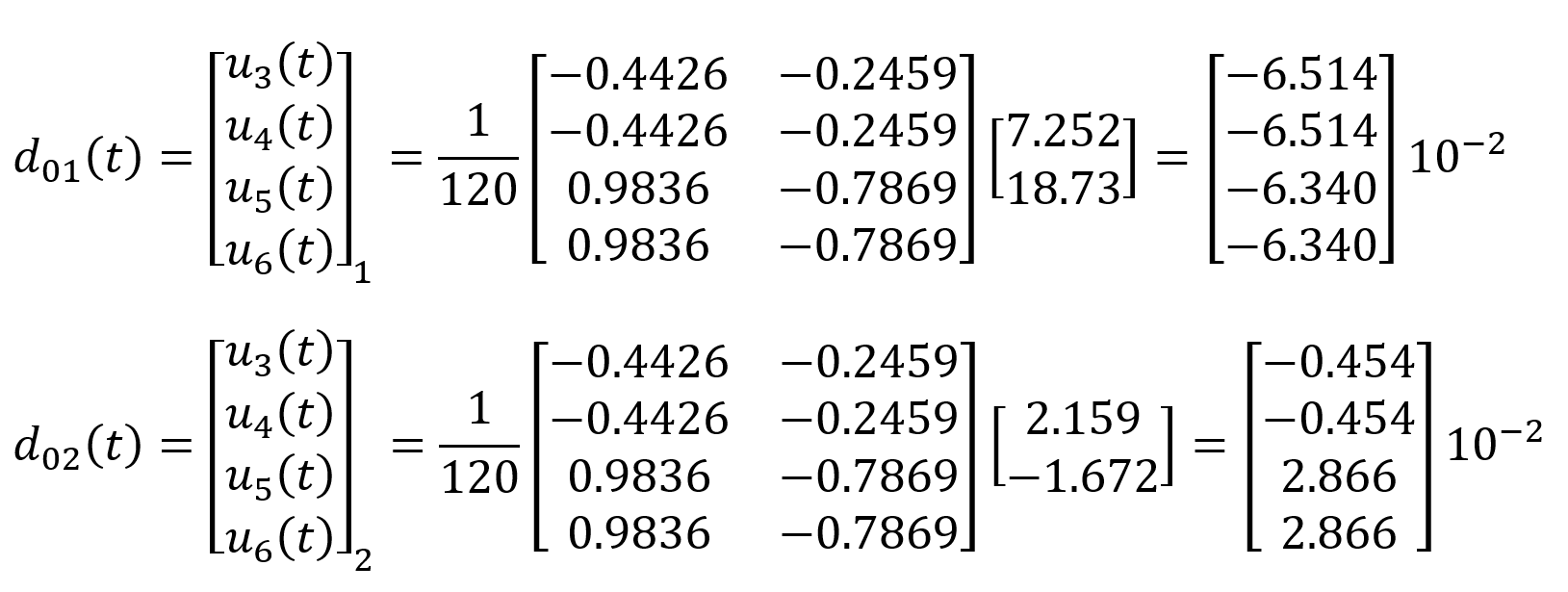
The vectors d 1 (t) and d 2 (t) are the reduced values of the modal shapes corresponding to the u 1 and u 2 freedoms. Similarly , the reduced deformation vectors d 01 (t) and d 02 (t) corresponding to the freedoms u 3 , u 4 , u 5 and u 6 for each mode are calculated as follows.
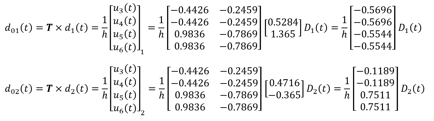
Here T is the transformation matrix. In this equation, D n (t) is the value of the nth vibration period corresponding to the defined horizontal elastic design displacement spectrum . A transition from the horizontal elastic design acceleration spectrum to the displacement spectrum is required.
From this point on, Full Quadratic Combination (TKT or CQC) can now be applied. 'Authentication vibration period T 1 = 1562 s and T 2 = 0.5868 was found.
To switch from the horizontal elastic design acceleration spectrum to the displacement spectrum, the following equation is used.
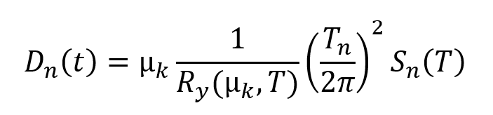
Note: In this example, no carrier system response coefficient will be used. Therefore, R y (µ k , T) = 1 and µ k = 1 will be considered. However, in the Design Based on Strength (DOT) approach, the carrier system behavior coefficient is taken into account.
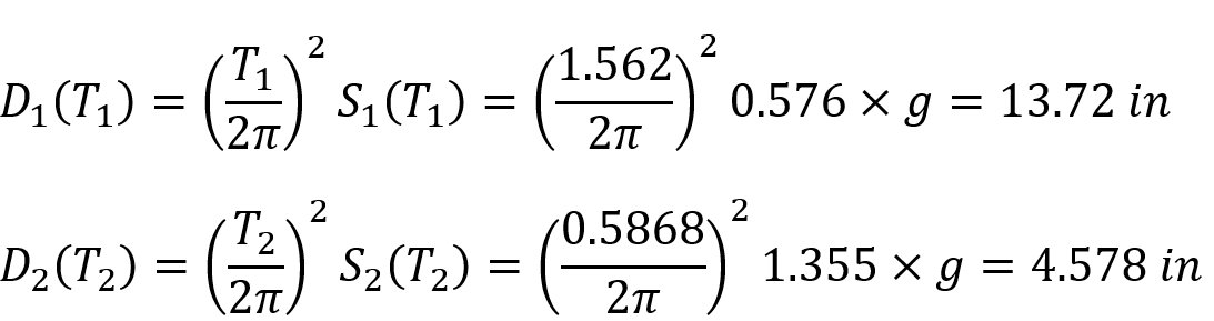
The spectrum values of the structure with straight vibration periods T 1 = 1.562 s and T 2 = 0.5868 were found as S 1 (T 1 = 1.562) = 0.576g and S 2 (T 2 = 0.5868) = 1.355g. In this case, the displacement spectra D 1 (T 1 ) and D 2 (T 2 ) are found as follows. Here, the acceleration of gravity is taken into account as g = 9.81 m / s 2 = 386.2205 in / s 2 .
After considering the horizontal elastic design spectrum, Full Quadratic Combination (TKT or CQC) , one of the Mode Combining Methods, is applied to find the deformations and internal force values of the structure .
Under the earthquake effect (for the X direction) 1st floor horizontal deformation value u 1st floor and 2nd floor horizontal deformation value u 2nd floor Full Square Combination (TKT or CQC) is calculated as follows.
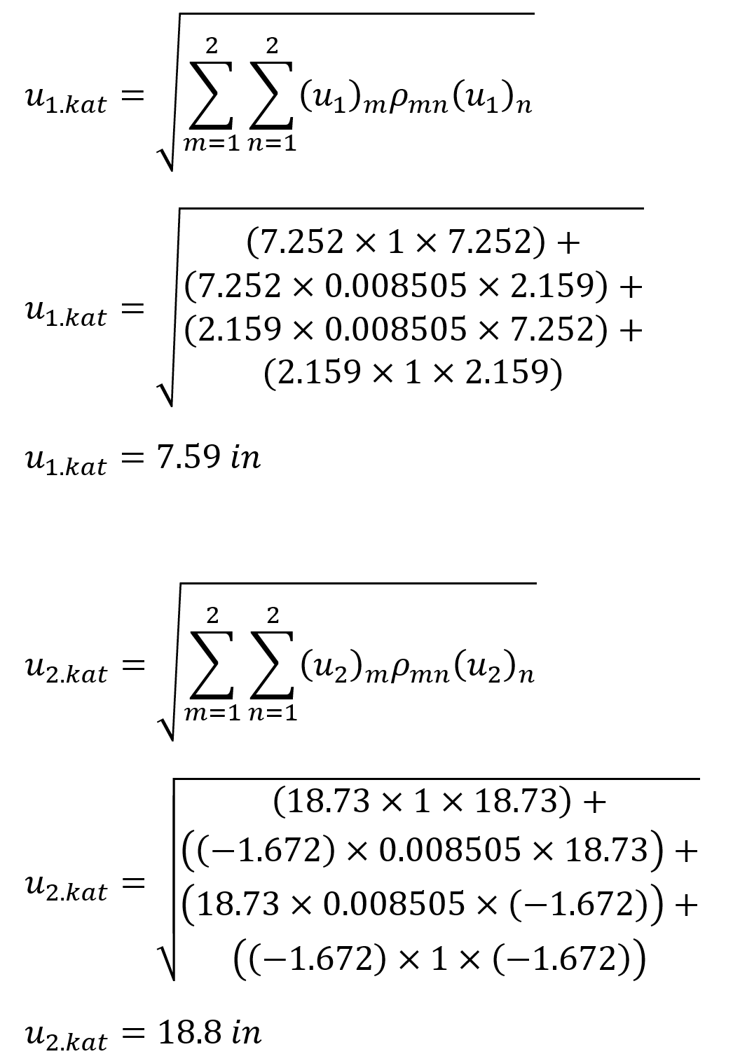
In this equation (u 1 ) n is the value of the substitution of u 1 in the nth mode, and d 1 is the first element of the (T n ) matrix. Since there are 2 modes in this example, there are 2 u 1 terms in the CQC equation . It is located in the Results, 1st floor horizontal deformation value of 1 floor and 2 times the horizontal deformation amount of the 2nd layer earthquakes the calculated displacement values. ρ mn is the cross correlation coefficient and it is calculated with the following formula for 5% damping ratio according to TBDY Equation 4B.5b .

In this equation, the damping ratio is taken as = 0.05. The coefficient β mn is the ratio of the m th and n th natural vibration periods.
The values of u 1st floor = 7.59 in and u 2nd floor = 18.8 are exactly the same as the results of ideCAD Structural.
Under the influence of an earthquake (for the X direction) element internal forces can be obtained similarly. The building moment diagram can be drawn in the order described below.
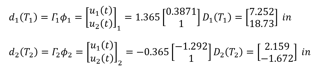
The translation and rotation displacements of the first mode and second mode, respectively, are given below.
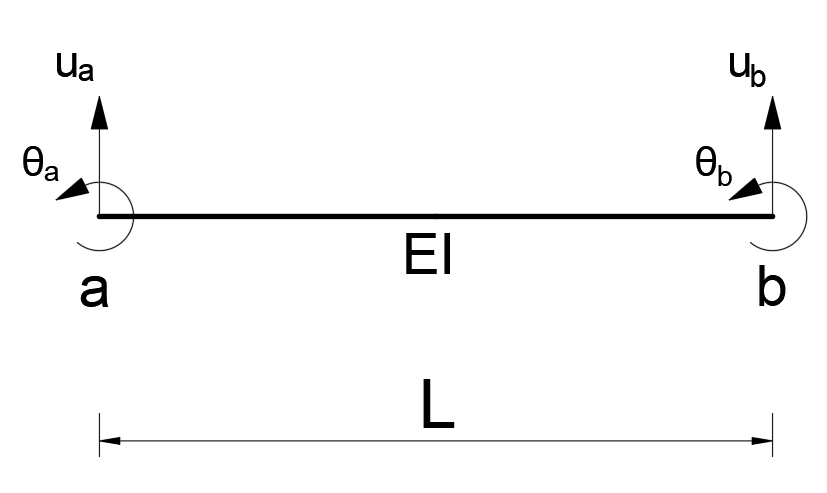
Knowing the tip displacements of a frame member of any EI stiffness and length L, the end forces of that member can be found. In the figure below, the end displacements of any frame element defined between joints a and b are given as u a , u b , θ a and θ b . Using these values, the moment value of the bar at joint a is found as follows.
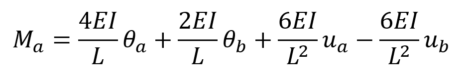
Using this information, the end moments of all frame members can be calculated for each mode.
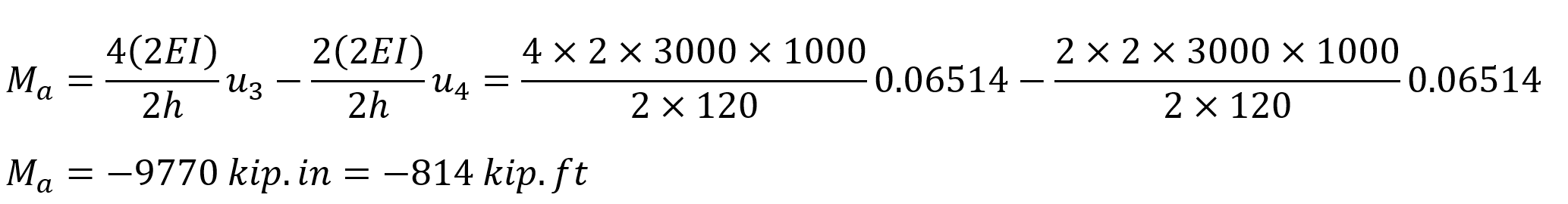
As an example, the moment value that occurs as a result of the 1st mode shape at the end of the 3 numbers of the beam between 3-4 joints can be calculated. In the above equation, the displacements of joint 3 instead of joint a and joint 5 instead of joint b , θ a = θ b = -0.06514 and u a = u b = 0 (no displacement in the Z direction) In this case, the value of M a is is calculated.
Using the matrices d 1 (t), d 2 (t), d 01 (t) and d 02 (t) for the above equation , the bending moment diagram for the first and second modal shapes is given below.
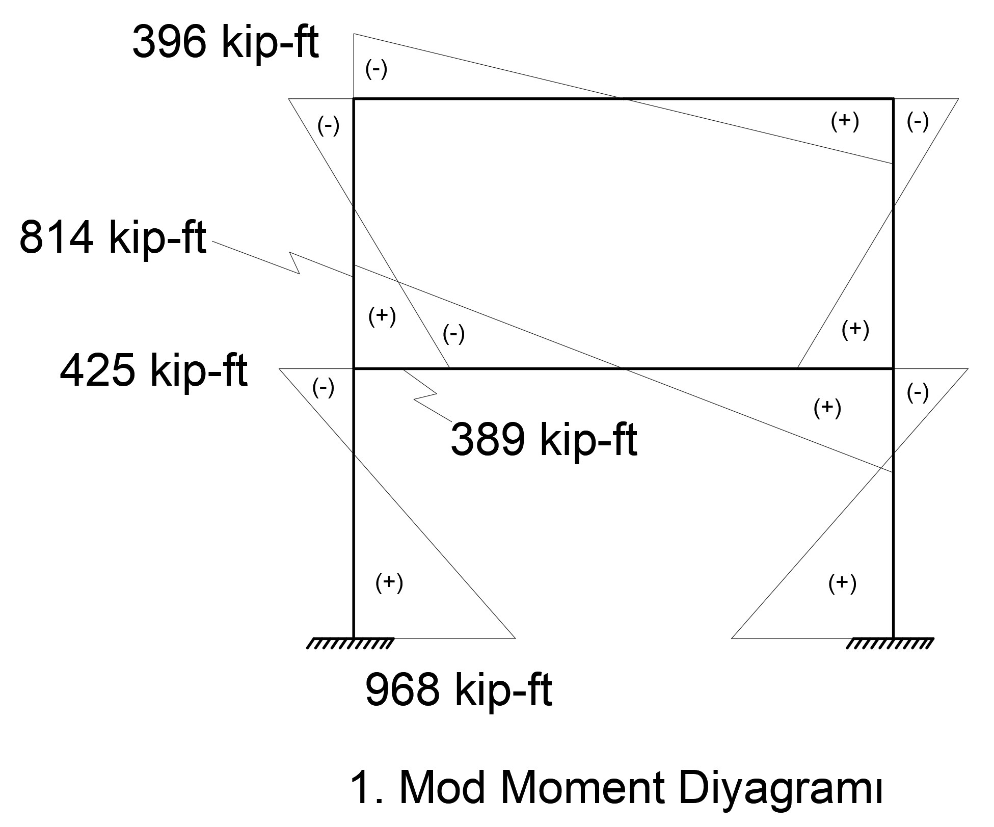
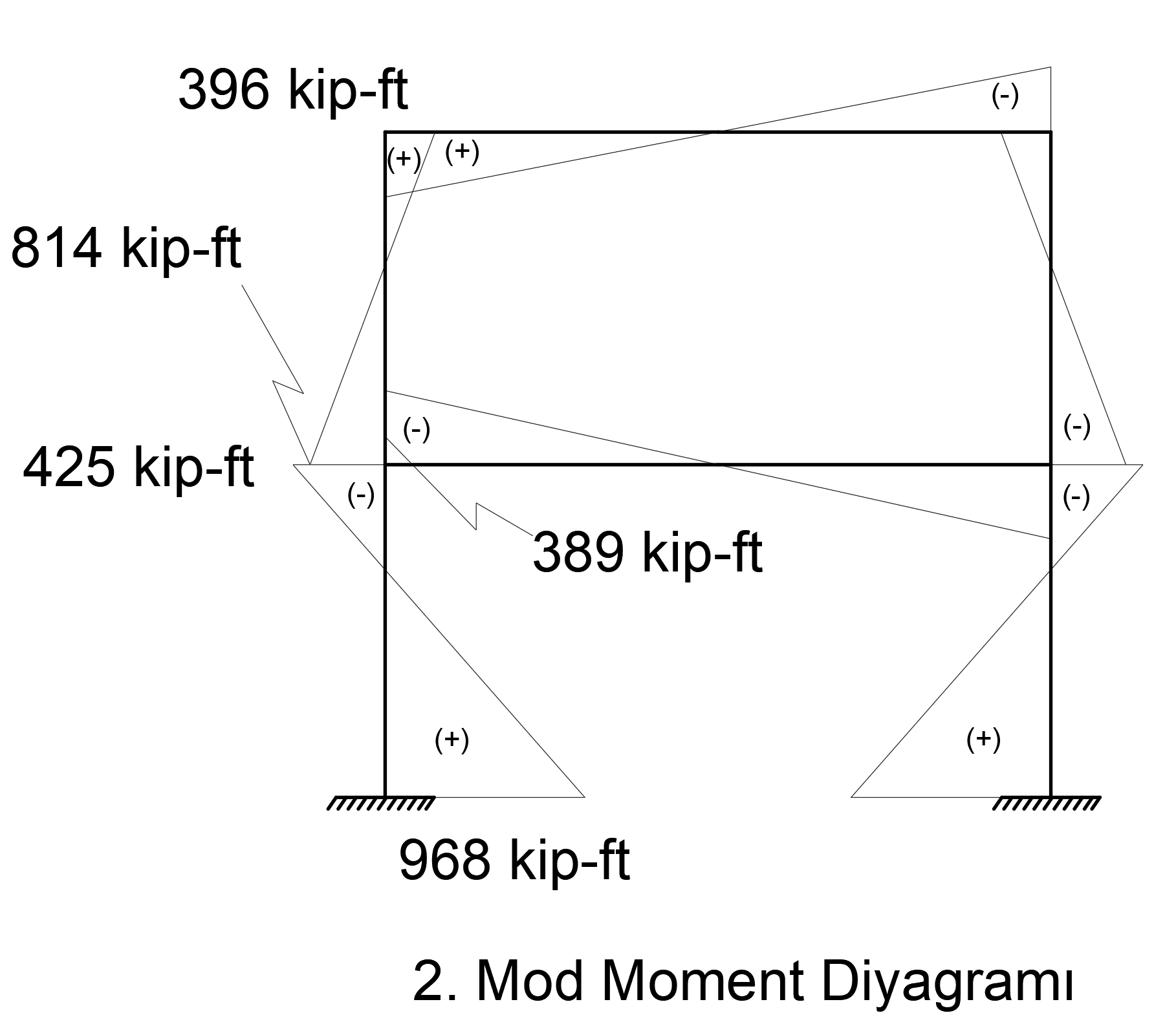
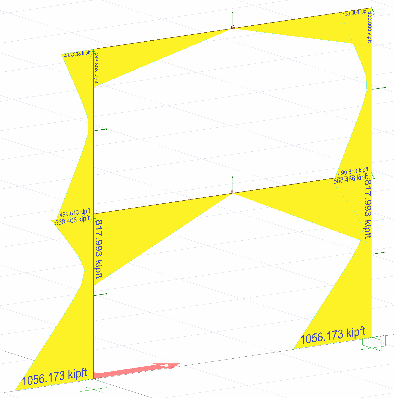
Elements and end moments are given in the table below when Full Quadratic Joining (TKT or CQC) is applied.
|
Workman |
Node |
1.Mod Moment kip-ft |
2.Mod Moment kip-ft |
CQC result kip-ft |
|---|---|---|---|---|
|
|
3 |
|
|
817.99 |
|
4 |
|
|
817.99 |
|
|
|
one |
|
179 |
433.81 |
|
2nd |
|
179 |
433.81 |
|
|
|
3 |
425 |
374 |
568.47 |
|
5 |
968 |
412 |
1056.17 |
|
|
|
one |
396 |
|
433.81 |
|
3 |
389 |
|
499.81 |
Moment values occurring in Ex loading are exactly the same with ideCAD Structural results.
Important Note: Complete Quadratic Combination (CQC or TKT) or square of the total of the
square root of (KTKK and SRSS) rules is a method in which the loss of the concept direction as seen in the example above. For this reason, internal forces and deformations are expressed in absolute values in the earthquake calculation made with the Mode Combination Method. The internal force diagrams drawn do not provide the equilibrium equation, they give the maximum internal force value that can occur due to all vibration modes of the relevant point under the effect of an earthquake.