
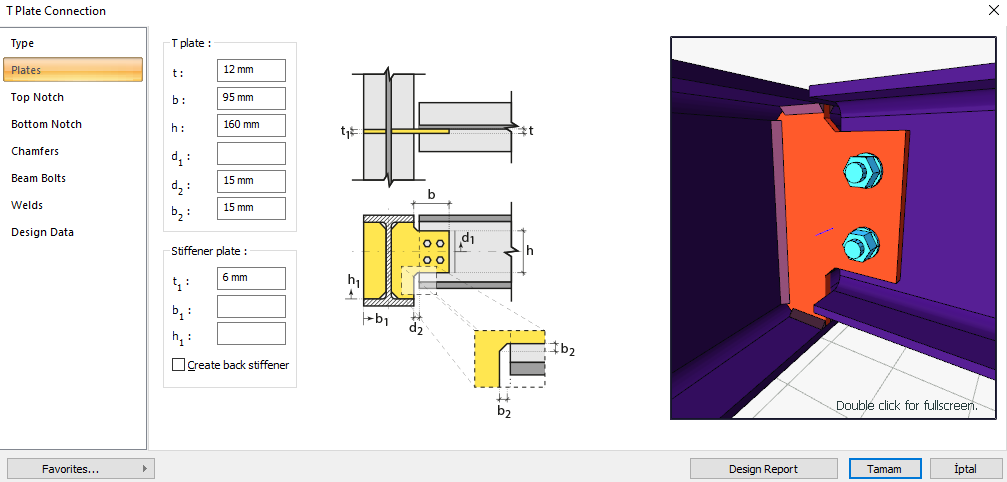
T plate connection is a type of non-moment-transferring connection (slip connection) that is bolted to the body of the profile and welded to the support. Bolt control, weld control and plate control are performed automatically according to the placement of the elements of the connection. Connection design with single plate is made automatically according to the Design, Calculation and Construction Principles of Steel Structures (ÇYTHYEDY) (GKT and YDKT) or AISC 360-16 (ASD and LRFD) regulations and the connection report is generated.
In the T plate connection calculation, distance control between bolts, horizontal and vertical edge distance control, weld thickness control, mounting stability controls are made as geometry control. As a strength control, checks are made for shear in the beam bolt, crushing in the beam and plate bolt holes, plate shear yielding, beam and plate shear failure, block slip in the plate, plate bending buckling, plate bending yield, support welding strength.
Connection Geometry
Geometry Checks
Bolt Spacing
|
|
ÇYTHYEDY 13.3.6 |
|
|
|
|
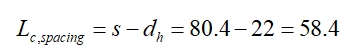
80.4 mm |
|
|
|
|
20 mm |
s =80.4 mm > smin = 3*20=60 mm |
√ |
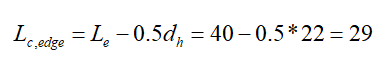
Horizontal Edge Distance
|
|
ÇYTHYEDY 13.3.7 |
|
|
|
|
40 mm |
L eh ≥ 2d = 2 * 20 = 40 mm conformity check for application |
√ |
|
|
26 mm |
Minimum distance check according to Table 13.9 |
√ |
Vertical Edge Distance
|
|
ÇYTHYEDY 13.3.7 |
|
|
|
|
40 mm |
L eh ≥ 2d = 2 * 20 = 40 mm conformity check for application |
√ |
|
|
26 mm |
Minimum distance check according to Table 13.9 |
√ |
Weld Thickness
|
|
ÇYTHYEDY 13.3.7 |
|
|
|
|
9 mm |
|
√ |
|
|
3.5 mm |
Table 13.4 |
√ |
Erection Stability
|
|
ÇYTHYEDY 13.3.7 |
|
|
|
L |
160.4 mm |
|
|
|
|
190.4 mm |
L=160.4 > 190.4/2=95.2 mm |
√ |
Strength Checks
Bolt Shear at Beam
|
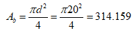
Ag
|
|
|
|
|
235.359 N/mm2 |
|
|
|
|
|
|
|
|
ÇYTHYEDY 13.17 |
|
|
|
|
|
Required |
Available |
Ratio |
Control |
|---|---|---|---|
|
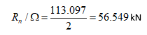
3.67 kN |
56,549 kN |
0.065 |
√ |
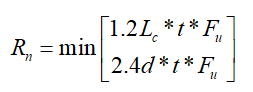
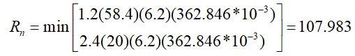
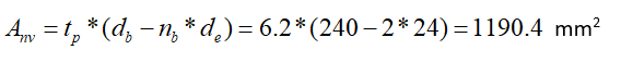
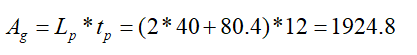
Bolt Bearing on Beam
|
|
20+2=22 mm |
|
|
t |
6.2 mm |
|
|
|
|
|
|
|
|
|
|
|
|
|
|
|
|
|
|
|
|
|
|
Required |
Available |
Ratio |
Control |
|---|---|---|---|
|
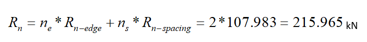
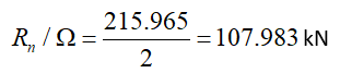
24.138 kN |
107.983 kN |
0.224 |
√ |
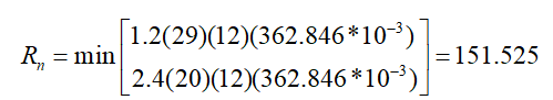
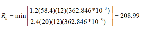
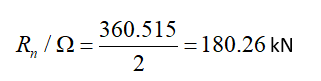
Bolt Bearing on Plate
|
|
20+2=22 mm |
|
|
t |
12 mm |
|
|
|
|
|
|
|
|
ÇYTHYEDY 13.3.13 Equation 13.14a and13.14b |
|
|
|
|
|
|
|
|
|
|
|
|
|
|

|
|
|
|
|
|
|
Required |
Available |
Ratio |
Control |
|---|---|---|---|
|
24.138 kN |
180.26 kN |
0.134 |
√ |
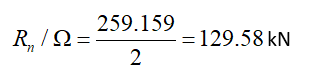
Beam Shear Rupture
|
|
|
|
|
|
362.846 N/mm2 |
|
|
|
|
ÇYTHYEDY 13.18 |
|
|
|
|
|
Required |
Available |
Ratio |
Control |
|---|---|---|---|
|
24.138 kN |
129.58 kN |
0.186 |
√ |
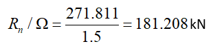
Plate Shear Yield
|
|
|
|
|
|
235.359 N/mm2 |
|
|
|

|
ÇYTHYEDY 13.17 |
|
|
|
|
|
Required |
Available |
Ratio |
Control |
|---|---|---|---|
|
24.138 kN |
181.208 kN |
0.133 |
√ |
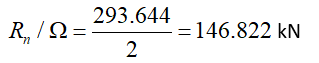
Plate Shear Rupture
|
|

|
|
|
|
362.846 N/mm2 |
|
|
|
|
ÇYTHYEDY 13.18 |
|
|
|
|
|
Required |
Available |
Ratio |
Control |
|---|---|---|---|
|
24.138 kN |
146,822 kN |
0.164 |
√ |
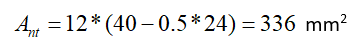
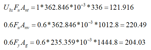
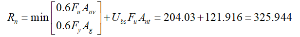
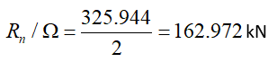
Plate Block Shear Rupture
|
|
|
|
|
|
|
|
|
|
|
|
|
|
235.359 N/mm2 |
|
|
|
362.846 N/mm2 |
|
|
|
one |
|
|
|
|
|
|
|
|
ÇYTHYEDY 13.19 |
|
|
|
|
|
Required |
Available |
Ratio |
Control |
|---|---|---|---|
|
24.138 kN |
162,972 kN |
0.148 |
√ |
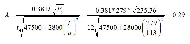
Plate Flexural Buckling
|
Fy |
235.359 N/mm2 |
|
|
t |
12 mm |
|
|
a |
60 mm |
|
|
L |
239 mm |
|
|
λ |
|
|
|
Required |
Available |
Control |
|---|---|---|
|
≤0.70 |
0.29 |
√ |
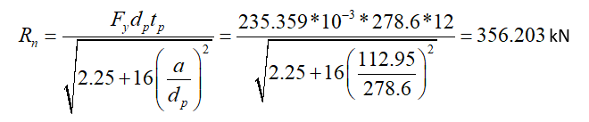
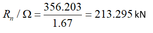
Plate Flexural Yield
|
|
278.6 mm |
|
|
|
235.359 N/mm2 |
|
|
|
12 mm |
|
|
|
112.95 mm |
|
|
|
|
|
|
|
|
|
|
Required |
Available |
Ratio |
Control |
|---|---|---|---|
|
24.138 kN |
213.295 kN |
0.113 |
√ |
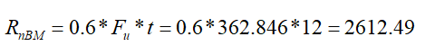
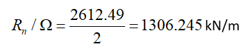
Weld Strength at Support
|
|
480000 kN/m2 |
|
in |
The weld thickness taken from the combination menu is 0.707 * w value. 9 / 0.707 = 12.73 mm |
|
|
362.846 N/mm2 |
|
t |
12 mm |
|
Rnw
|
|
|
|
|
|
|
|
|
|
|
|
Required |
Available |
Ratio |
Control |
|---|---|---|---|
|
0.015 kN/m |
1306.245 kN/m |
1.15 * 10 (-5) |
√ |
Next Topic
Related Topics