
-
Effective section stiffnesses are automatically taken into account in accordance with the elements.
-
For buildings to be built, the effective section stiffness of concrete structural system elements is taken into account according to TBDY 5.4.2.4 or TBDY 4.5.8 , under the control of the user.
ICONS
d b = Diameter of longitudinal reinforcement (average in tensile) [m]
(EI) e = Effective section stiffness of column, beam, tie beam or curtain modeled according to the agglomerated plastic behavior
f y = Average (expected) yield strength of reinforcing steel [MPa]
f ce = Average (expected) compressive strength of concrete [MPa]
h = Section height [m]
L s = Shear opening [m]
M y = Effective yield moment [kNm]
ϕ y = Curvature of yield [m -1 ]
θ y = Flow Status to the axis of rotation likelihood disposition [rad]
η = in the calculation of the first rotation Pour beams and columns, curtains received coefficient 0.5
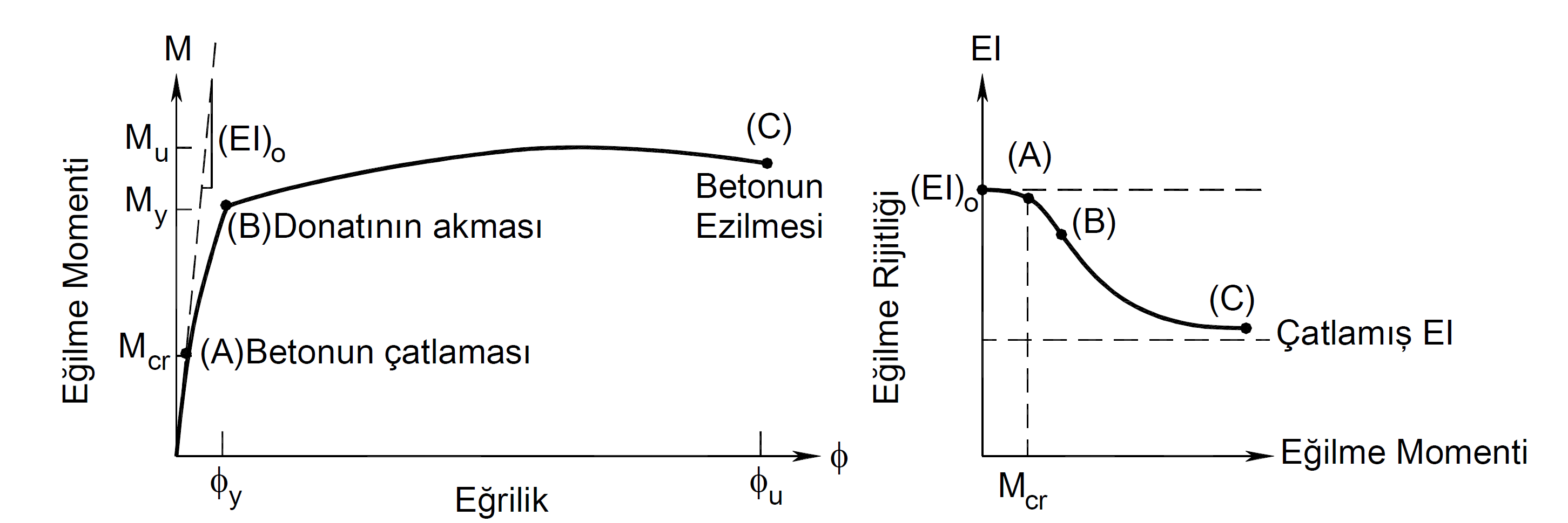
In reinforced concrete elements, the bending stiffness varies depending on the level of the moment acting on the section. With the cracking of the section, the bending rigidity decreases. With the increase in bending moment, the bending stiffness decreases to the fractured section bending stiffness. There is a significant difference between cracked and uncracked section stiffness.
The effective cross-section stiffness of the elements modeled linearly along the length remaining between reinforced concrete plastic joints according to TBDY Article 5.4.2.4 shall be determined according to Section 5.4.5 of TBDY . In TBDY Section 5.4.5 , effective section stiffnesses are found in Equation (5.2) .

Equivalent. (5.2) expresses the effective section stiffness for elements modeled according to the lumped plastic behavior . Here, M y is the average of the effective yield moments in the rod element. In a component whose moment-curvature relationship is calculated, the moment of yield, M y means the moment at the point where the tensile reinforcement flows, and is the moment value shown at point (B) in the picture below. The reinforced concrete element section is calculated by M y moment curvature relation according to the reinforcement placement and material model . ( Concentrated Plasticity Model )Concentrated Plasticity Model
Denk. (5.2) 'de belirtilen My çubuk elemanındaki etkin akma momentlerinin ortalamasıdır. Bu durumda kesitin donatı yerleşimine göre ( + ) ve ( - ) yönünde farklı değerler hesaplanır. Örneğin bir kesitin kuvvetli ekseninde (3 ekseni) etkin kesit rijitliği hesaplanırken moment eğrilik bağıntısı +3 ekseni etrafında oluşturulur ve My(+3) değeri bulunur. Benzer şekilde moment eğrilik bağıntısı -3 ekseni etrafında oluşturulur ve My(-3) değeri bulunur. İtme analizinde kesitin 3 eksenindeki etkin kesit rijitliğini (eğilme rijitliği) hesaplamak için kullanılan etkin akma momentlerinin ortalaması olan My(3) değeri, My(+3) ve My(-3) değerlerinin ortalaması olarak gözönüne alınır.
My(3) = [ My(+3) + My(-3) ]/2
Benzer işlemler 2 ekseni etrafındaki eğilme rijitliği için ayrı hesaplanır.
θy etkin akma dönmelerinin ortalamasını ifade etmektedir ve tek bir yön için Denk.(5.3) ile hesaplanır. Etkin akma dönmelerinin ortalaması θy , ilgili eksen etrafında ( + ) ve ( - ) yönde farklı değerler hesaplanır ve ortalaması alınır.

Burada ϕy plastik mafsal kesitinde ilgili yöndeki etkin akma eğriliğini göstermektedir. Moment-eğrilik bağıntısı hesaplanan bir plastik mafsalda etkin akma eğriliği, çekme donatısının aktığı noktadaki eğrilik anlamına gelmektedir. Yukarıdaki resimde ( B ) ile gösterilen noktadaki eğrilik değeridir. (Concentrated Plasticity Model )
Ls kesme açıklığı olarak isimlendirilmektedir. Kolon ve kirişlerde açıklığın yarısı olarak dikkate alınmaktadır.
h kesit yüksekliği değeridir ve eğilme momenti doğrultusundaki (eğilme moment vektörüne dik doğrultuda) yükseklik dikkate alınır.
db, donatı çeliklerinin ortalama çapı, fce and f to the concrete of the average (expected) shows the average yield strength of the reinforcement and compressive strength. Detailed explanation for f ce and f to f value has been made under the heading General Modeling.
As described above, the effective cross-section stiffness is calculated automatically in the elements modeled according to the piled plastic behavior . Equation (5.2) and Equation (5.3) are calculated separately for each element.
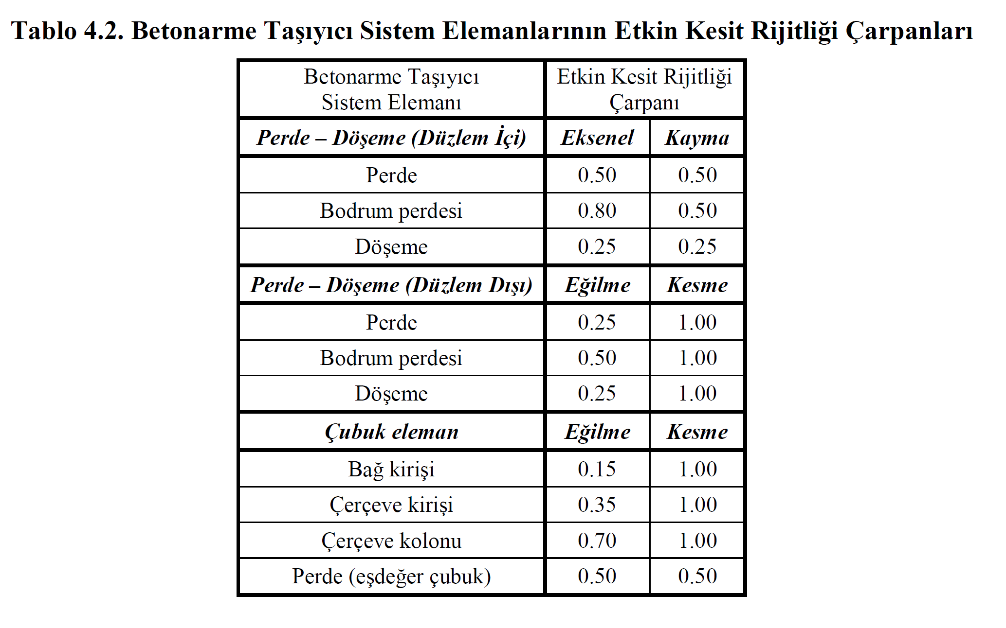
In the concrete elements defined in the new buildings, the effective section stiffness of the elements modeled linearly along the length between the plastic hinges can also be determined according to Table 4.2 specified in TBDY Section 4.5.8 . This option is at the discretion of the user.
Next Topic