
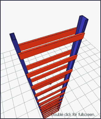
With the Column-Column Connection (Built Up Column) command, two columns are combined according to the given knitting type.
Location of Column-Column Connection (Built Up Column) Command
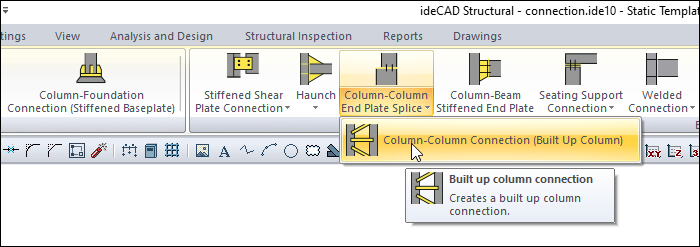
You can access it under the ribbon menu, Connection tab, Experimentals title.
Usage Steps
-
From the Steel menu, click on the Experimentals/Column-Column Connection (Built Up Column) line.
-
In a 3D perspective view, click the first, then the second, of the columns to be joined.
-
The connection will occur with default settings.
-
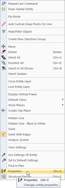
Double-click the connecyion to change settings.
-
The built up column connection dialog will open.
Location of the Built Up Column Connection Dialog
Select the connection and click the right mouse button. Click the Properties line from the right click menu that opens.
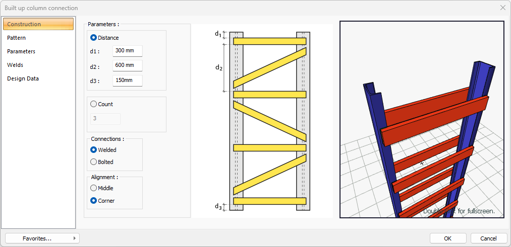
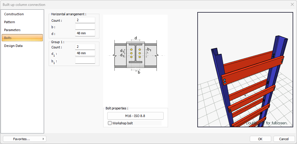
Built Up Column Connection Dialog
Construction Tab
|
Specifications |
|---|
|
Distance 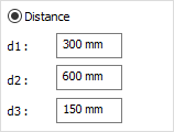
By selecting the option, patterns are determined by entering the plate distance values. The values to be entered are shown in the schematic drawing. |
|
Count 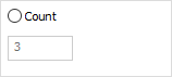
By checking the option, patterns are determined by entering the count. The values to be entered are shown in the schematic drawing. |
|
Connection 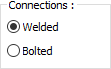
Welded or bolted types are selected for plate connection. |
|
Alignment 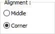
Alignment of the plates according to the column is determined by choosing one of the middle or corner options. |
|
Schematic drawing 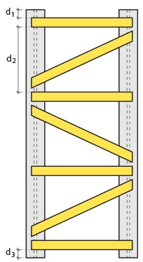
Connection and plate values are shown on the schematic drawing. |
|
Preview 
There is a preview of the connection. The selection made and the entered values can be followed simultaneously in the preview. |
Pattern Tab
|
Specifications |
|---|
|
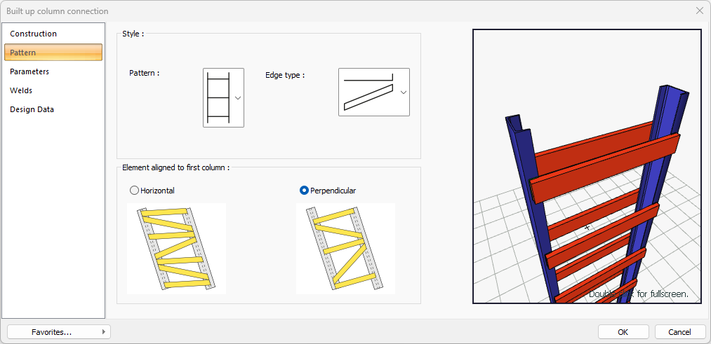
Pattern 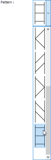
One of the listed pattern types is selected. |
|
Edge type 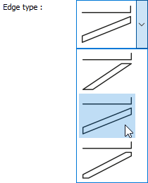
One of the listed edge types is selected. |
|
Element alignment to first column 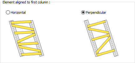
Element alignment to the first column is determined by checking the horizontal or perpendicular option. |
|
Preview
There is a preview of the connection. The selection made and the entered values can be followed simultaneously in the preview. |
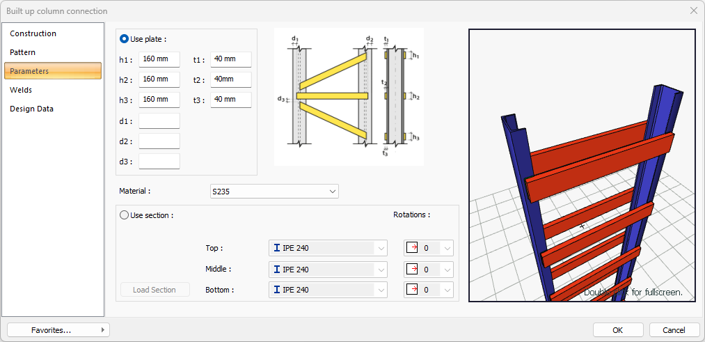
Parameters Tab
|
Specifications |
|---|
|
Use plate 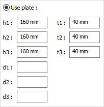
If the option is selected, it is determined by entering the plate values. The values to be entered are shown in the schematic drawing. |
|
Material The material is selected for the created sheet. |
|
Use section 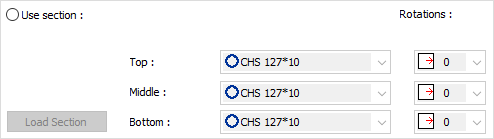
By selecting the option, one of the ready profiles is selected from the lists as a plate. By clicking on the Load section button, you can reach the ready section library and reach the list of American and European finished rolling sections and select from the list. The selected profile can be rotated if desired. |
|
Schematic drawing 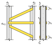
Connection and plate values are shown on the schematic drawing. |
|
Preview
There is a preview of the connection. The selection made and the entered values can be followed simultaneously in the preview. |
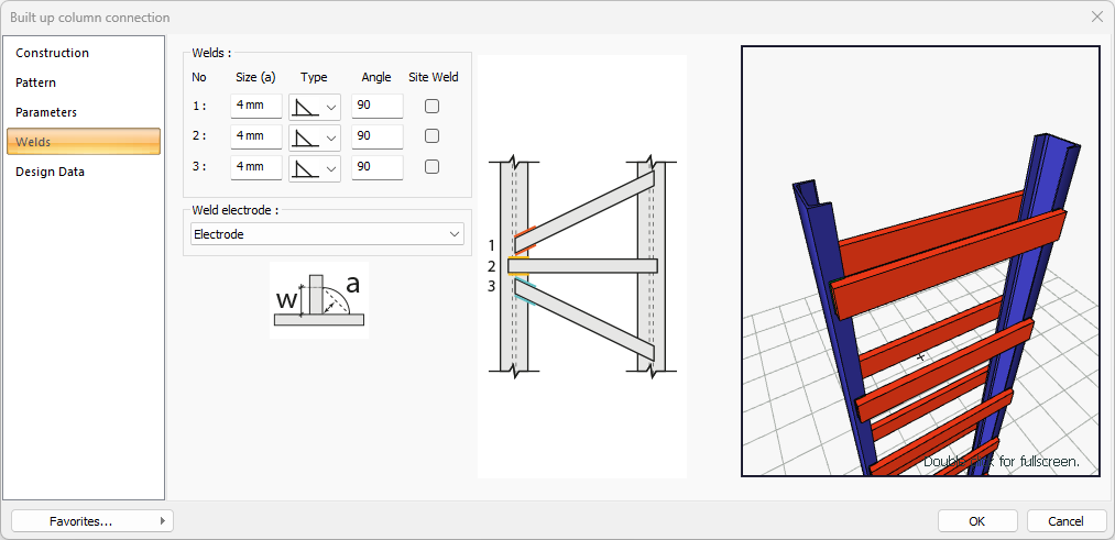
Welds Tab
This tab appears when the welded is marked in construction tab.
|
Specifications |
|---|
|
Welds 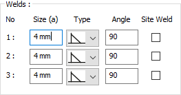
The thickness, type and angle values of the welds to be made at the connections are given. The information on whether it will be done on the construction site or not is entered. |
|
Weld electrode The strengths of the welding electrodes are defined in the design inputs. The strength of the main element in the weld joint is controlled under the condition that it has less strength than the weld strength. If necessary, click the list and define "Create New…". To create the welding electrode, give the information "Name" and "Weld metal tensile strength" in the dialog that opens after clicking "Create New". Welding geometry is determined automatically by the program. These properties can be changed to easily determine the connection properties. Geometry features are in accordance with industry standards and in the form specified in AISC. |
|
Schematic drawing 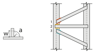
Connection and weld values are shown on the schematic drawing. |
|
Preview
There is a preview of the connection. The selection made and the entered values can be followed simultaneously in the preview. |
Bolts Tab
This tab appears when the bolted is marked in construction tab..
|
Specifications |
|---|
|
Horizontal arrangement 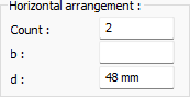
The horizontal arrangement distance value of the bolts is entered. The values to be entered are shown in the schematic drawing. |
|
Group 1 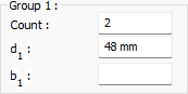
Distance values of bolts are entered. The values to be entered are shown in the schematic drawing. |
|
Bolt properties 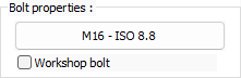
The Hole and Bolt Parameters dialog is opened by clicking on the bolt properties button. The bolt properties are set in this dialog. |
|
Schematic drawing 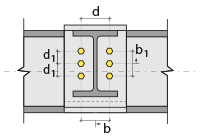
Connection and bolt placement values are shown on the schematic drawing. |
|
Preview 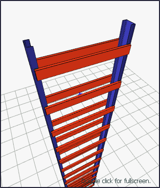
There is a preview of the connection. The selection made and the entered values can be followed simultaneously in the preview. |
Design Data Tab
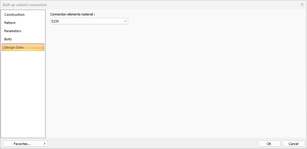
In the design data, the connection elements material is defined. The condition that the main element in the weld joint has less strength than the weld strength is controlled.
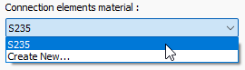
If necessary, click the list and define "Create New…". To create the connection elements material, give the information material definitions and values in the dialog that opens after clicking "Create New".
Next Topic