
-
The shear force in the column-beam joints in the earthquake direction considered is automatically calculated with Eq (7.11) .
-
Equivalent. (7.12) and Equation. The shear force limits in confined and unconfined joints given in (7.13) are automatically controlled.
-
The minimum transverse reinforcement conditions in the column-beam junction are automatically applied in accordance with the conditions given in 7.5.2.3 (a) and (b) .
ICONS
A s1 = Total area of the tensile reinforcement placed on one side of the column-beam node to accommodate the negative moment of the beam
A s2 = Thetotal area of the tensile reinforcement placedon the other side of thecolumn-beam node withrespectto A s1 to accommodate the positive moment of the beam
b j = In the earthquake direction considered, if the beam stuck in the joint area is the same width as the column or protrudes from both sides of the column, the column width, otherwise, twice the distance from the vertical middle axis of the beam to the column edges (the beam width cannot exceed the sum of the height of the junction)
b w = beam width of the body
f ck = concrete characteristic cylindrical compressive strength
f yk = resistance to flow characteristic of longitudinal reinforcement
h = cross section dimension in the earthquake direction Considering the Column
V e = column, beam, combination of and taken as a basis shear of transverse reinforcement accounts curtain
V Arm = Thesmaller of the column shear forces calculated according to Section 4 above and below the node point
ϕ = Reinforcement diameter
Shear Safety of Column-Beam Joints
The design shear force in the column-beam junction area in the earthquake direction considered is calculated by Equation 7.11 .

In this relation, A s1 is the total area of the tensile reinforcement placed on one side of the column-beam node to meet the negative moment of the beam, and A s2 is the total area of the tensile reinforcement placed on the opposite side of the column-beam node A s1 to meet the positive moment of the beam. represented as space. V arm, on the other hand , represents the shear force which is smaller than the column shear forces calculated considering the vertical loads above and below the joint and the Strength Excess Coefficient D.
Figure 7.10 shows the situations in which the V arm value is found, A s1 and A s2 reinforcement areas.
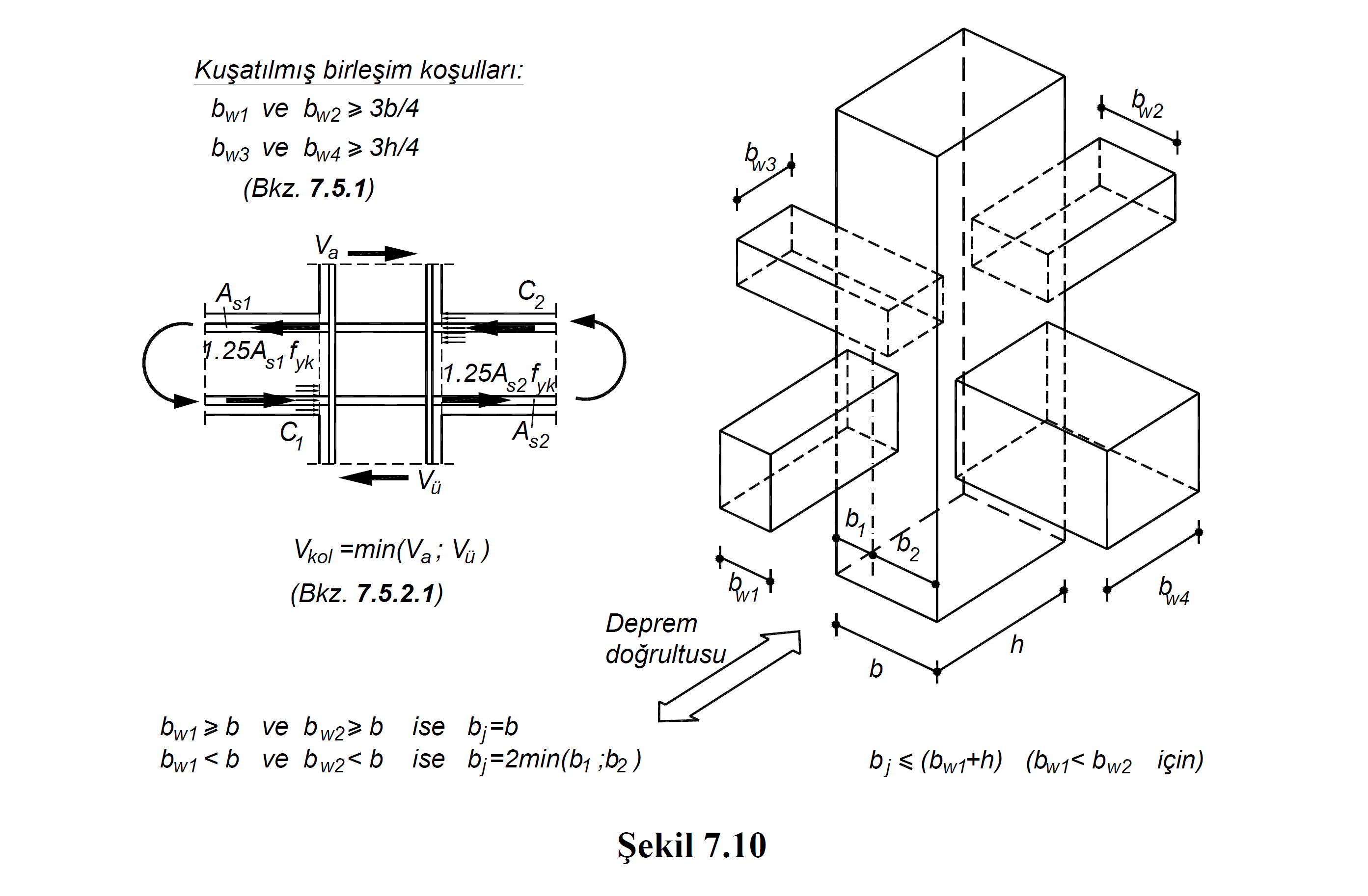
V a value is the shear force value calculated at the lower point of the column above the node, taking into account the vertical loads and the Strength Excess Coefficient D. V ü value is the shear force value calculated at the upper point of the column below the node, taking into account the vertical loads and the Strength Excess Coefficient D. V arm value is the smaller of V a and V u cutting forces.
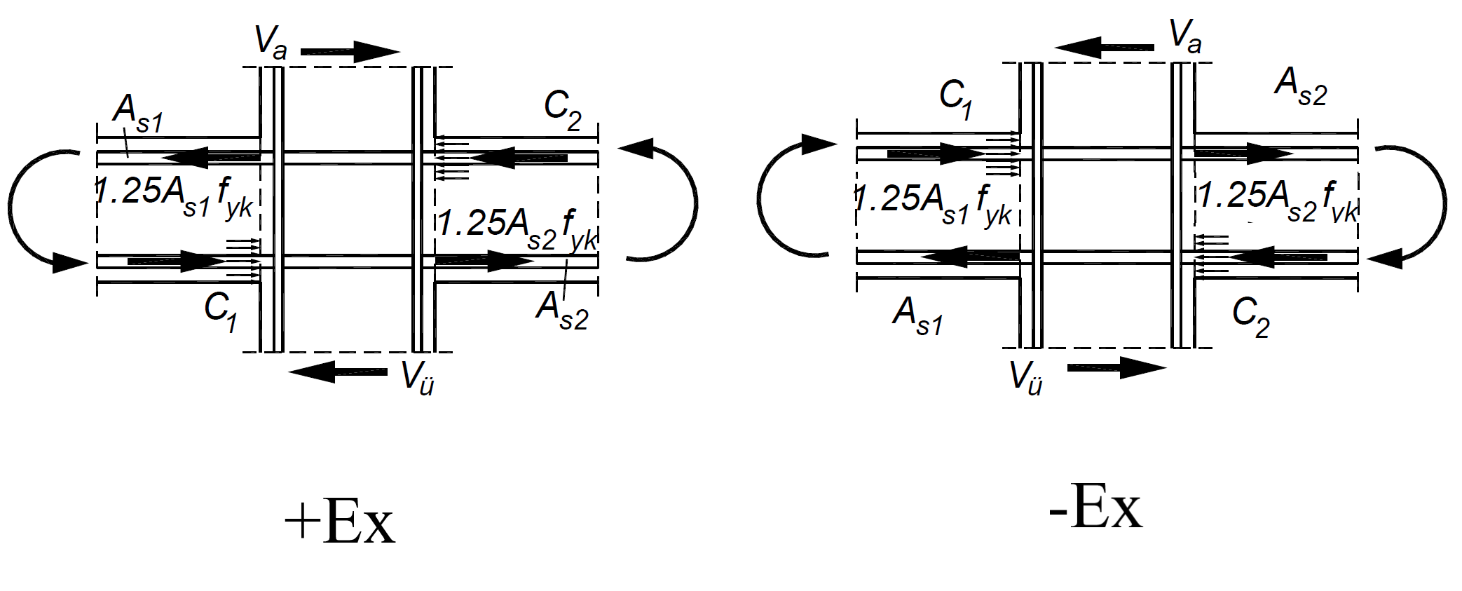
In Figure 7.10 , A s1 and A s2 reinforcement areas are shown as a representative single earthquake direction. A s1 and A s2 reinforcement areas are calculated separately according to the positive and negative earthquake effect and the most unfavorable condition is taken into account. For example, for earthquake in the + Ex direction , if the upper reinforcement receives the tensile effect due to the moment effect on the left beam A s1 , then the lower reinforcement receives the tensile effect due to the moment effect on the A s2 right beam. However, when the direction of the earthquake changes, the direction of the moment will also change, so the reinforcement under tensile effect also changes. For this reason, for an earthquake in the -Ex direction, A s1 is the lower reinforcement area in the left beam, while As2 becomes the upper reinforcement area on the right beam.
In the Column-Beam Connection Area Shear Safety report, this situation is shown according to the most unfavorable condition. Ex and Ey results shown under the heading Load (+/-) in the sample report below were made separately for the positive and negative directions and the most unfavorable condition was reflected in the report. In the report , together with the reinforcement areas A s1 and A s2 , the V arm value in the relevant direction and the design shear force V e values for the junction area calculated by Equation 7.11 are also shown.
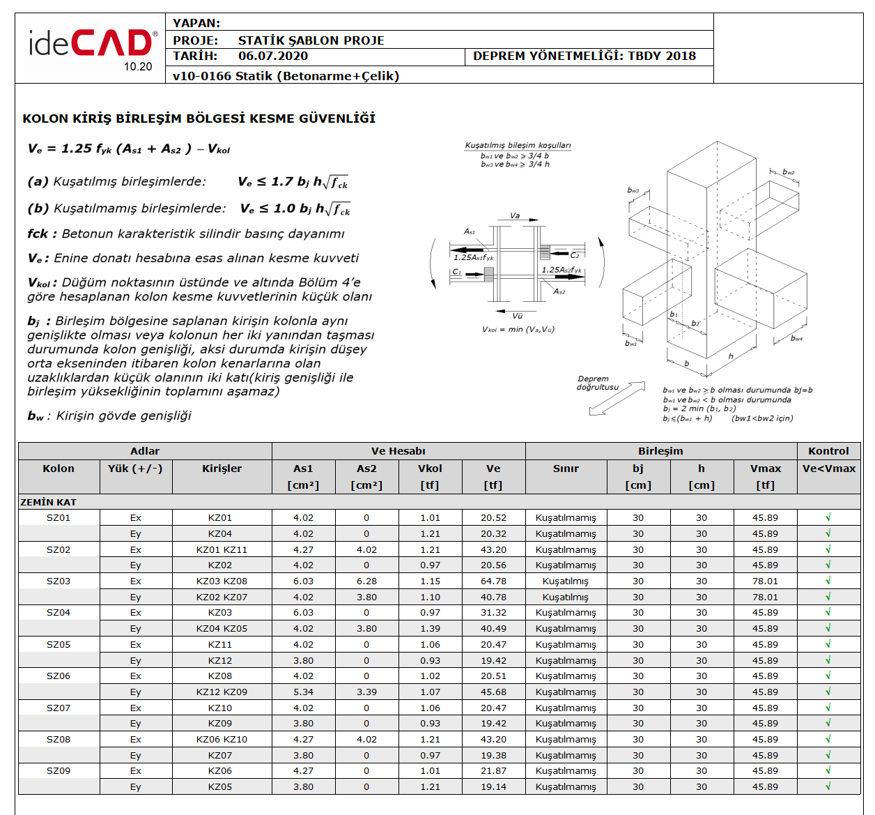
7.11 Equation combination of design shear is calculated by V e , in combination flanked equation 7.12, in unconfined joint equation 7.13 is compared with the limit values.


If the limit values of Equation 7.12 and Equation 7.13 are exceeded according to the classification of the joint zone, the earthquake calculation should be repeated by increasing the cross-section dimensions.
In the equations of Equation 7.12 and Equation 7.13 , b j In the earthquake direction considered, if the beam stuck in the joint area is the same width as the column or protrudes from both sides of the column, the column width, otherwise, from the vertical center axis of the beam to the column edges, the column width is twice the value of the smaller one. . The calculation of this value is shown in Figure 7.10 . The value of h indicates the cross-section dimension of the column in the direction of the earthquake. f ck is the characteristic cylinder compressive strength of concrete.
Next Topic