
|
The project, which was prepared with ideCAD Architectural, was opened with ideCAD Structural. You can download the project and interfere with the structural system. |
-
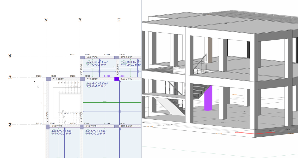
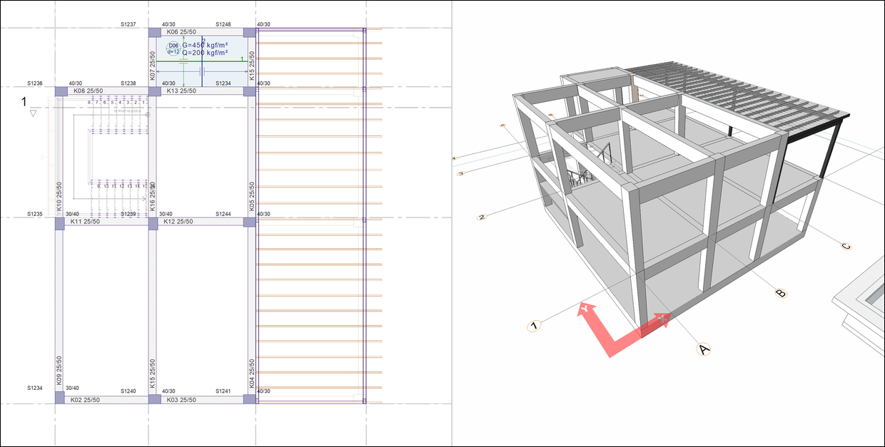
Click on the column command.
-
Click on the C-3 axis intersection. Rotate the column so that the 40 cm side of the column is on axis 3.
-
Move upper right corner of the column to the C-3 axis intersection with the spacebar.
-
Place the column by clicking the left button.
-
Warning is given that the column divides an architectural mode entity..
-
Click the OK button to close the window.
-
Press the Esc key on the keyboard to exit the command.
-
Delete the slabs D02 and D03.
-
Click on the beam command.
-
Click on the C-1 axis intersection as the starting point.
-
Press the spacebar to slide the beam to the left side of the axis C.
-
Click on the C-3 axis intersection as the ending point.
-
Beams are formed between axes 1-3.
-
Press the Esc key on the keyboard to exit the command.
-
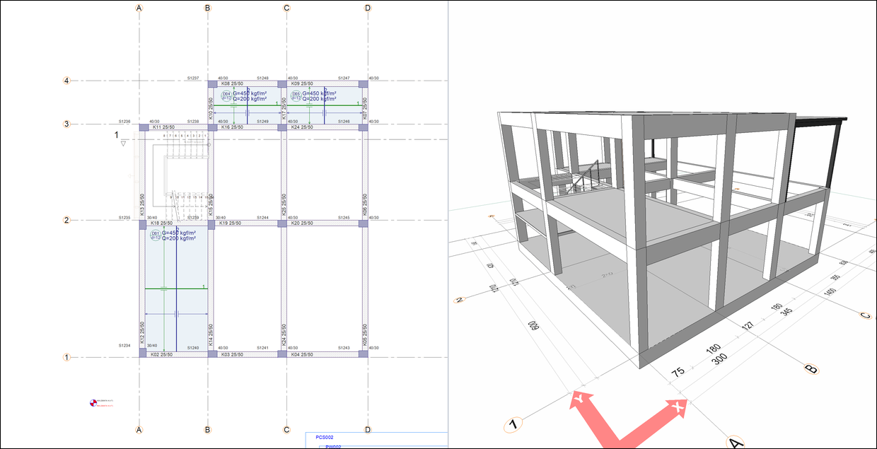
Click on the Slab command.
-
Move your mouse over the area delimited by axes 1-2 and B-C and click the left button.
-
Move your mouse over the area delimited by axes 1-2 and C-D and click the left button.
-
Move your mouse over the area delimited by axes 2-3 and B-C and click the left button.
-
Move your mouse over the area delimited by axes 2-3 and C-D and click the left button.
-
Slabs are formed.
-
Press the Esc key on the keyboard to exit the command.
-
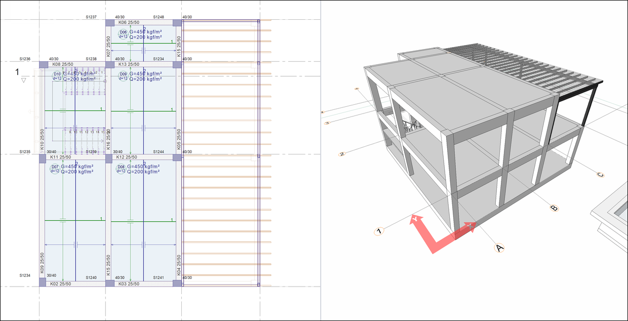
Open the STORTY 1 CEILING page.
-
Click on the column command.
-
Click on the C-3 axis intersection. Rotate the column so that the 40 cm side of the column is on axis 3.
-
Move upper right corner of the column to the C-3 axis intersection with the spacebar.
-
Place the column by clicking the left button.
-
Press the Esc key on the keyboard to exit the command.
-
Delete slabs D01 and D02.
-
Click on the beam command.
-
Click on the B-1 axis intersection as the starting point.
-
Press the spacebar to slide the beam to the left side of the axis B.
-
Click on the B-3 axis intersection as the ending point.
-
Beams are formed between axes 1-3.
-
Press the Esc key on the keyboard to exit the command.
-
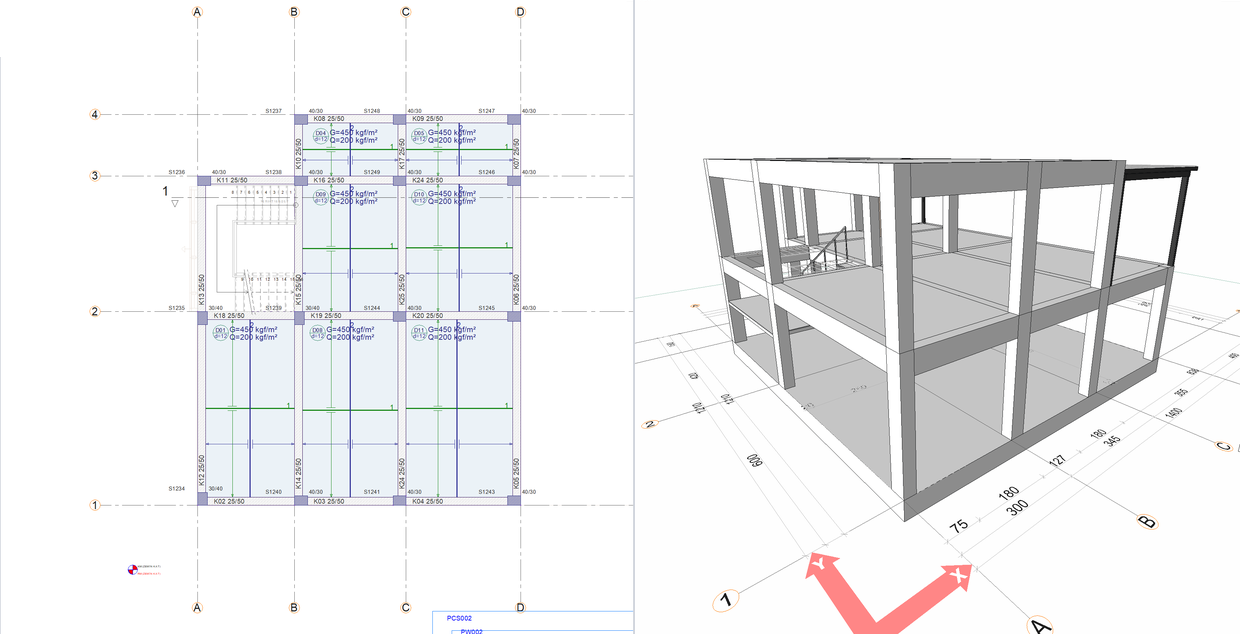
Click on the Slab command.
-
Move your mouse over the area delimited by axes 1-2 and A-B and click the left button.
-
Move your mouse over the area delimited by axes 2-3 and A-B and click the left button.
-
Move your mouse over the area delimited by axes 1-2 and B-C and click the left button.
-
Move your mouse over the area delimited by axes 2-3 and B-C and click the left button.
-
Slabs are formed.
-
Press the Esc key on the keyboard to exit the command.
-
Turn off Advanced Snap from the Quick Access Toolbar.
-
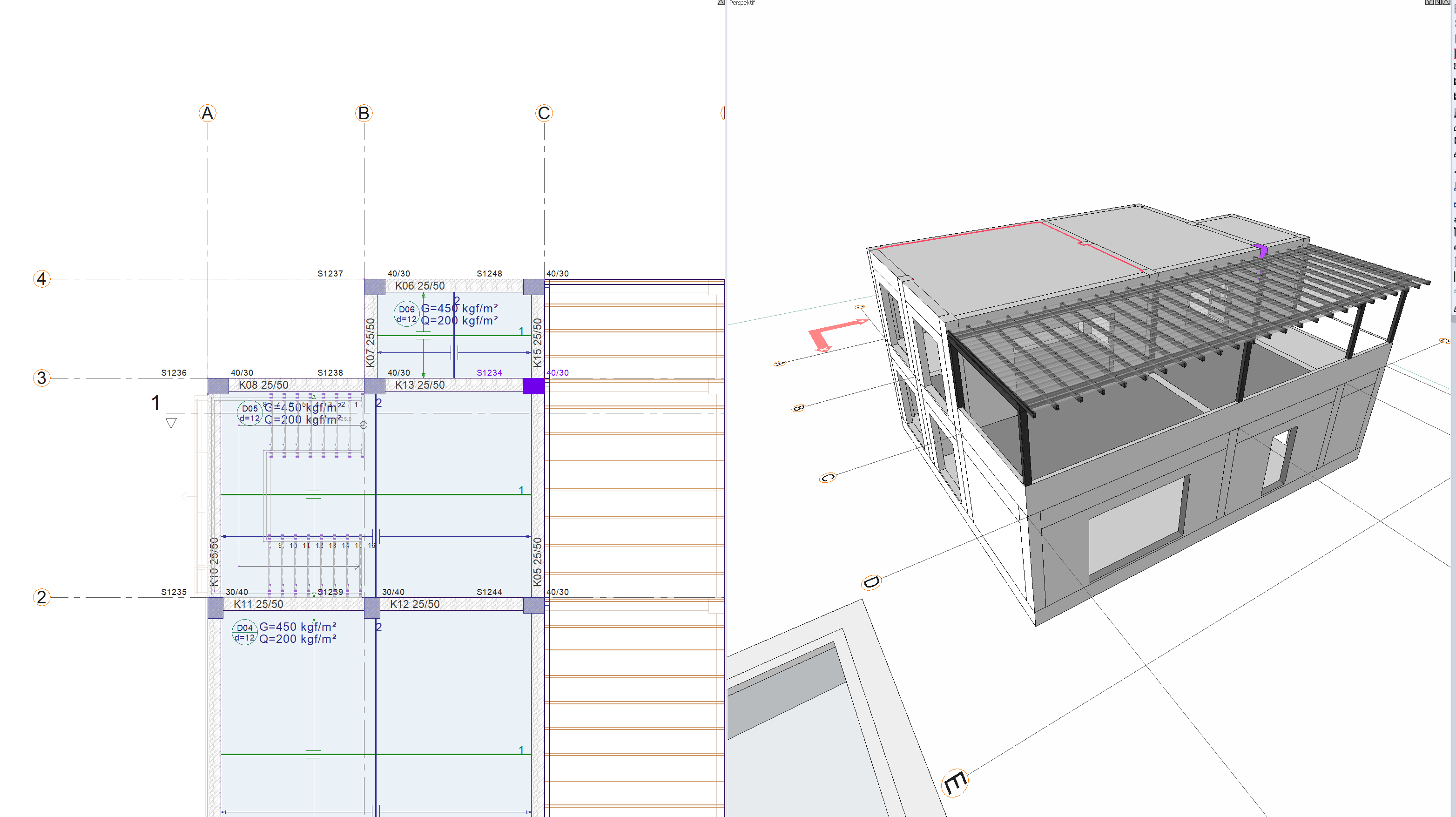
Click on the Steel Beam command.
-
Select the RHS 100*150*4 section from the steel beam toolbar section list.
-
Approach the steel columns in perspective.
-
Click on the top node of the steel column at the D-2 axis intersection.
-
Click on the top node of the steel column at the C-2 axis intersection.
-
Press the Esc key on the keyboard to exit the command.
-
Click on the Steel Beam command.
-
Click on the top node of the steel column at the D-3 axis intersection.
-
Click on the top node of the steel column at the C-3 axis intersection.
-
Steel beams are formed.
-
Press the Esc key on the keyboard to exit the command.
-
Open the BASE STORY CEILING page.
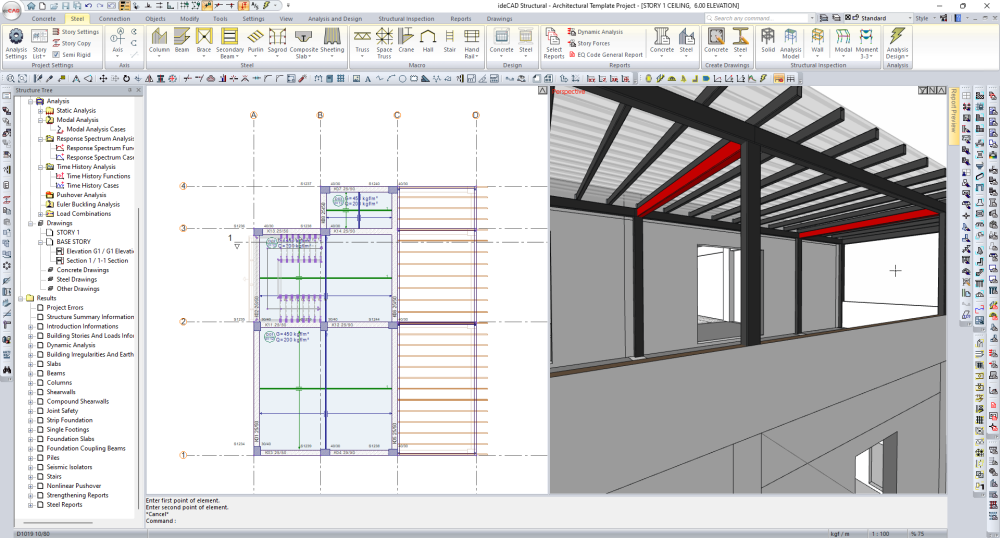
Follow the steps of the video below.
Next Tutorial