
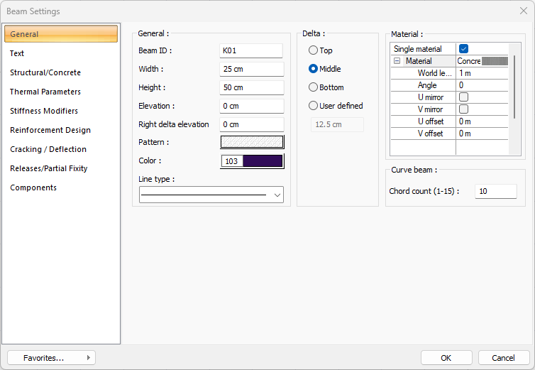
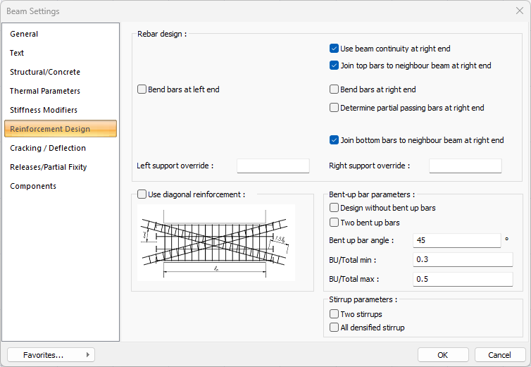
With the Beam Settings command, settings such as the size, drawing, placement, material selection, structural material of the concrete beam can be accessed.
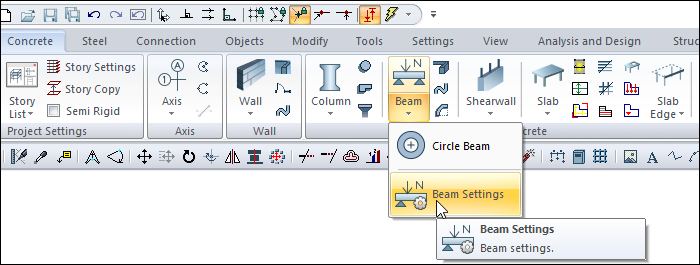
Location of Beam Settings Dialog
Beam, which appears on the screen after the beam command runs, is also available in the auxiliary toolbar.
Also, it can be accessed by clicking on the Concrete tab Concrete title.
General Tab
|
Specifications |
|---|
|
Beam ID The beam ID is visible and can be changed. The name written here appears when the beam is created, and the number increases by one for each new beam. K01, K02, K03 etc. |
|
Width/Height The width and height of the beam is determined in these boxes. |
|
Elevation/Right delta elevation The elevation and right delta elevation parameters are used to determine the height at which the beam will be placed in the floor plan. While the elevation value determines the elevation of the entire beam, the right end elevation determines the elevation of only the right end joint of the beam. Inclined beams in the Z plane can be defined by entering different values into these boxes. Beams with zero elevation value are modeled on the floor ceiling. Beams such as intermediate landing beams can be drawn by giving a negative value. Beams such as reverse beams can be defined by postvaluing. |
|
Pattern It is the hatch type that applies to the beam. Clicking on pattern opens the Pattern Option dialog. Select the type of hatch from the look-up chart in this dialog. |
|
Color The beam is the color of the border lines. A selection is made on the color palette that is opened by clicking and holding down the left mouse button. |
|
Line Type Line type of the line forming the beam is selected in the plan. Clicking the down arrow buttons to the right of the boxes opens the list of line types. From this list, the desired line type is selected by clicking the left mouse button. |
|
Delta 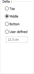
These are the options that determine where the beam will be defined. If the virtual beam axis that connects the joints at the two ends of the beam will coincide with the top edge of the beam, the top is selected, if it coincides with the bottom edge, the bottom option is selected, and if it passes through the middle of the beam, the middle option is selected. If the virtual beam axis will pass through another line, the Defined option is selected and the distance to the top edge of the beam is entered in the lower data entry box. The distance given should not be more than the beam thickness. Top, bottom and middle alignment values can be adjusted by pressing the space key on the keyboard after determining the first joint of the beam during data entry. 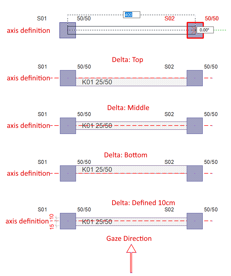
|
|
Material 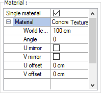
The material to be used on the surfaces of the shearwall is selected from the list. Surfaces are covered with the selected material and displayed as such in renderings. Texture length is entered into the world length. For example; If 1 is entered, the selected material texture is taken as 1 meter and covered on the relevant walls. In the angle, the angle of the texture is entered. Touch the U and V offset. The motion value in the x and y plane is entered. With U and V mirroring, the texture is symmetrical with respect to the y and x planes. By selecting the single material option, the material selected in "Front material" is used on all surfaces of the beam |
|
Curved beam/Chord count (1-15) 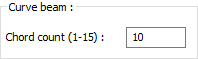
Determines the drawing precision of curved beam. As the number of points increases, the curved beam becomes more curvilinear. In order to create a single piece angled beam, a definition can be made by entering the number of curved beam points 1. 
|
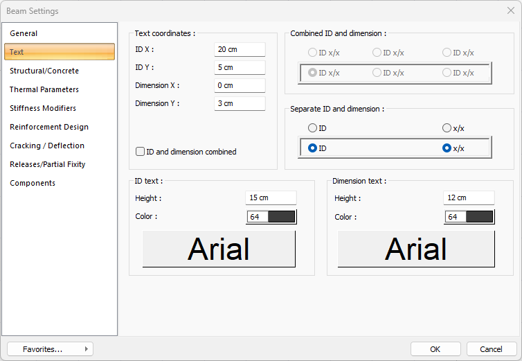
Text Tab
|
Specifications |
|---|
|
ID X/ID Y X and Y coordinates are entered according to the beam upper left corner of the Beam Name text. Text If the X value is positive, the name text will move to the left, if it is negative, it will move to the right. Text scrolls up if the Y value is positive, and scrolls down if it is negative. |
|
Size X / Size Y X and Y coordinates are entered according to the upper right corner of the beam of the Beam Dimension text. If the dimension X value is positive, the dimension text shifts to the left, if it is negative, it shifts to the right. If the dimension Y value is positive, the dimension text will scroll up, and if it is negative, it will scroll down. |
|
ID and dimension combined If checked, the beam ID and dimension are written together. If not checked, the beam ID and beam dimension are written in the marked places in the dialog. |
|
Combined ID and dimension 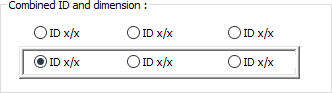
When the name and size together option is selected, determine the position where the name and size of the beam will be written according to the shape in the dialog. The ideCAD will place the name according to the location chosen when the beam was created. |
|
Separate ID and dimension 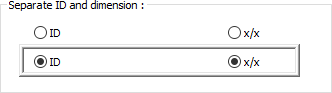
When the name and size together option is not checked, determine the position where the beam name and size will be written according to the shape in the dialog. The ideCAD will place the name according to the location chosen when the beam was created. |
|
Name Letter Height, Color and Font 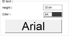
The height of the beam IDtext is entered. The color box is selected from the color palette that is opened by clicking the left mouse button. If the text button just below is clicked, the Font Settings dialog opens. From this dialog, Beam ID Text, font is set. |
|
Size Font Height, Color and Font 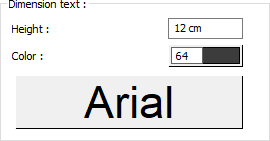
The height of the beam dimension text is entered. The color box is selected from the color palette that is opened by clicking the left mouse button. If the button below is clicked, the Font Settings dialog opens. From this dialog, Beam Dimension Text, font is set. |
Structural/Concrete Tab
|
Specifications |
|---|
|
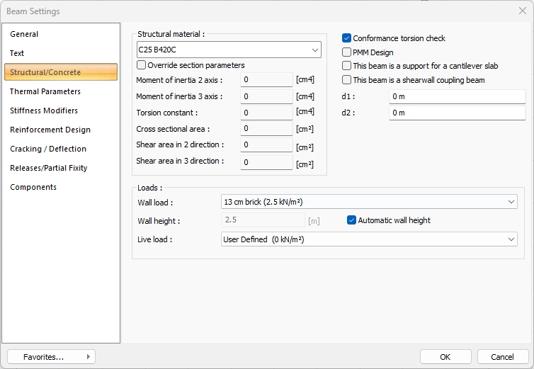
Structural material Select the structural material to be used in the beam element from the list. Structural material can be defined as a reinforced concrete element under Materials in Building Tree. |
|
Override section parameters 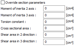
The section and geometric properties of the element are determined automatically and these are the values in accordance with the regulations. However, if you want to change the element section properties, mark this line and give the relevant values to the ideCAD. The ideCAD automatically calculates zero values and accepts non-zero entries as much as the entered value. 2 axis moment of inertia The element is the minor moment of inertia. I = b 3 h / 12
3 axis moment of inertia The element is the major moment of inertia. I = bh 3 /12 50/25 For example, in a column three axis rectangular moment of inertia 50.50.50.25 / 12 = 260416 cm 4 is calculated as. Torsional moment of inertia It is the moment of inertia that defines the torsional stiffness of the element. Cross-sectional area It is the cross-sectional area value of the element. For example, in a 50/25 rectangular column, the cross section area of the element is 50.25 = 1250 cm 2 . Cutting area in 2 direction The element is the cutting area in the minor direction. Cutting area = 5/6. b. d For example, in a 50/25 rectangular column, 5 / 6.50.25 = 1041 cm2 Cutting area in 2 direction The element is the cutting area in the major direction.
|
|
Conformance torsion check When marked, the torsion control in the beams is checked according to the conformity torsion condition. Td = Tcr is taken. When unchecked, the beam is checked for its equilibrium torsion. Tcr = Torsional cracking strength of the section Td = torque value used in control Conformity torsion = If the presence of torsional moment in a system is not necessary for equilibrium, that is torsional fitness torsion. If the option is not selected, the torsion control in the beams is controlled according to the condition of the balance torsion. Td = Tdhesap Td = torque value used in control Tdhesap = Largest design torsion moment found after analysis Equilibrium torsion = Torsion is equilibrium torsion if the structural element and the system need torsional moment to maintain balance. |
|
PMM design With the PMM design option, beam design is made with the interaction of axial force and biaxial bending. |
|
This beam is a support for a cantilever slab If the beam cantilever is the support of a floor, this option can be selected. Otherwise, it should not be marked. |
|
This beam is a shearwall coupling beam If the option is selected, it ensures the automatic implementation of the commitment degree control in TBDY 2018 Article 4.5.4, regardless of the length / height ratio of the beams between the two walls. If the option is unchecked, the ideCAD automatically applies the degree of adherence control for beams between two walls, with length and height ratio less than 5 (l / h ≤5). You can see these beams under the heading of tie beam degree in the general report of the earthquake regulation. Also, whether cross reinforcement design can be made or not according to TBDY 2018 Article 7.6.8 depends on this option. In order to apply "cross reinforcement", the option of cross reinforcement should also be selected. |
|
d1 Specifies the distance of the rigid arm at the left support of the beam. This value is calculated automatically by the program. Leave it as zero unless a custom value is needed. |
|
d2 Specifies the distance of the rigid arm at the right support of the beam. This value is calculated automatically by the program. Leave it as zero unless a custom value is needed. |
|
Wall Load You can select the appropriate wall load from the list. The wall loads in the list are those defined in the load library. If you want to specify a value other than these values as wall load, you can select the user-defined line from the list and enter the appropriate value from the dialog that opens. You can also add new wall loads to the load library yourself. |
|
Wall height Enter the height of the wall you want to be taken into account on the beam. |
|
Automatic wall height If this line is marked, the wall height to be considered on the beam is calculated automatically. Wall height = Story height - Upper story beam height Note: If a wall is defined on a beam, a wall load must be defined in the wall settings. |
|
Live load The appropriate live load is selected from the list. |
TBDY 2018 Tab
|
Specifications |
|---|
|
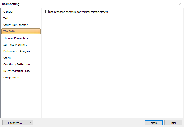
Use response spectrum for vertical seismic effects If it is marked, it is applied to the selected elements considering the vertical elastic acceleration spectrum according to the reference materials specified in Article 4.4.3.1 of TBDY 2018. These effects appear as a combination of Ez (R). When unchecked, the vertical earthquake effect is calculated from the formula Ez (G) = 2/3 * SDS * G according to the principles specified in Article 4.4.3.2 of TBDY and these effects appear as a combination of Ez (G). |
Thermal Parameters Tab
|
Specifications |
|---|
|
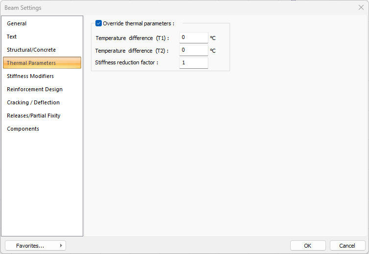
Override thermal parameters When checked, it activates T1 and T2 temperature loads on element basis. |
|
Temperature difference (T1) The temperature difference of T1 loading is given. |
|
Temperature difference (T2) The temperature difference of the T2 loading is given. |
|
Stiffness reduction factor The stiffness reduction factor to be used in the temperature calculation for the relevant element is given. |
Stiffness Modifiers Tab
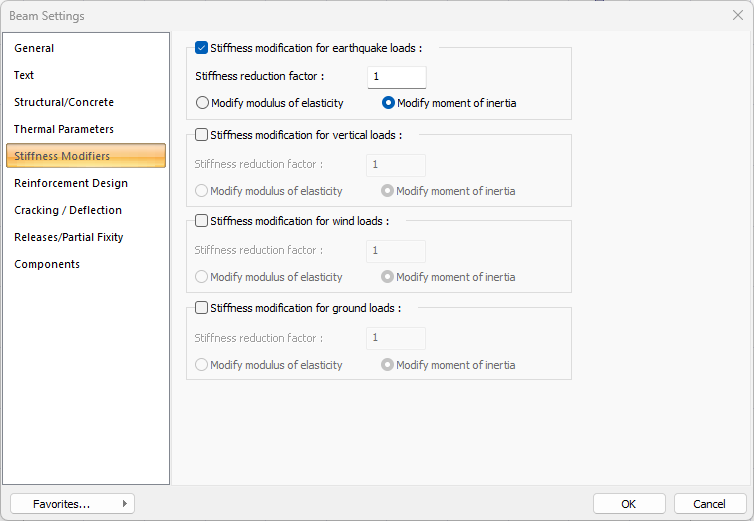
This tab is only visible when the beams are selected and the Object Properties and beam settings are opened. In this tab, beam stiffness can be reduced by a specific anchor value separately for earthquake, vertical, wind and soil thrust loads. Stiffness reduction can be applied optionally on the basis of the element elasticity modulus or moment of inertia.
|
Specifications |
|---|
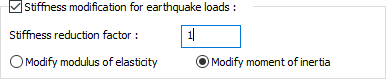
Beam stiffness can be reduced by a specific anchor value separately for earthquake, vertical, wind and soil thrust loads. Stiffness reduction can be applied optionally on the basis of element elasticity modulus or moment of inertia. E = Reduction Factor * E or I = Reduction Factor * Applied as I. |
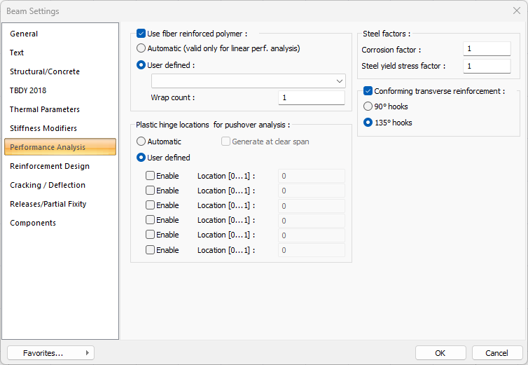
Performance Analysis Tab
|
Specifications |
|---|
|
Use fiber reinforced polymer 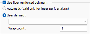
In columns that will be reinforced with fibrous polymer, Fibrous polymer properties are set by checking this option. Reinforcement is made by selecting one of the fibrous polymers defined in the Fibrous Polymer Library and the number of windings. |
|
Corrosion factor It is a ratio used in building performance analysis. With the ratio written on this line, the wear occurring in the existing structures and reinforcements exposed to the corrosion conditions specified in the earthquake regulation can be taken into account in the performance calculation of the structure. The value defined in this row is multiplied with the existing reinforcement areas and the value found at the result of multiplication is considered as the reinforcement area. The mevcutal the yenial = multiplier * |
|
Steel yield stress factor It is used to reduce the steel yield stress of the elements. The value entered in this row is multiplied by the steel yield value of the element. yeniçelikakmadeğer * mevcutçelikakmadeğer of the multiplier = |
|
Conforming transverse reinforcement 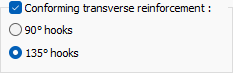
If there is stirrup tightening at the upper and lower ends of the column of the existing structure, this option is selected. When this option is selected, it is assumed that the columns have confined concrete behavior. To define the hook angle of the stirrups in the tightening area of the existing column, one of the 90˚ or 135˚ hook options should be selected. |
|
Plastic hinge locations for pushover analysis 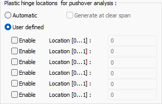
Plastic hinge locations for pushover analysis can be determined automatically or manually. |
Reinforcement Tab
|
Specifications |
|---|
|
Bend bars at left end If the beam is not continuous, the reinforcements are drawn in a square on the relevant support. If the beam is continuous, the reinforcements are also drawn continuously. This option allows the reinforcement to be set square even if the beam is continuous. The rebars are folded into the column on the left column support. |
|
Use beam continuity at right end If the beam is continuous, the continuous beams will automatically be the same continuous and this option is automatically checked. If the option is deselected, the canceled beam will not be drawn continuously and will be detached from the adjacent beam at the right end. For example, let's consider a 2 span continuous beam system. Normally for the 1st span, the option "always accept beam at right end" is selected. If the mark is removed, the 1st and 2nd beams are drawn as separate parts. |
|
Join top bars to neighbour beam at right end In continuous beams, the upper reinforcements are arranged in one piece to ensure the 12-meter condition whenever possible. If this option is not selected, top reinforcements are placed by cutting on the support. |
|
Bend bars at right end If the beam is not continuous, the reinforcements are drawn in a square on the relevant support. If the beam is continuous, the reinforcements are also drawn continuously. This option allows the reinforcement to be set square even if the beam is continuous. The rebars are folded into the column on the right column support. |
|
Determine partial passing bars at right end This option, which is set for continuous but different beams, regulates whether a certain proportion of the rebars will be transferred to the other beam. In two continuous beams of different widths, if this option is selected, the reinforcement transition is arranged by taking into account the ratio found from the section of beam widths. For example, let the width of the 1st beam 50 cm and the width of the 2nd beam 25 cm. 25/50 = 0.5 ratio. The number of reinforcement, for example, is 4 straight reinforcement. 2 pieces of reinforcement will make partial transition, and 2 pieces of reinforcement will be cut with a square. |
|
Join bottom bars to neighbour beam at right end In continuous beams, straight reinforcements are arranged in one piece to ensure the 12-meter condition whenever possible. In short, it is passed on the lower bearing without any additional. If this option is not selected, flat reinforcements are placed in the support by cutting. |
|
Left support override/Right support override If a beam is supported to the junction point of more than one panel, it is determined from these boxes which panel will be drawn as the support of this beam in the drawings. The appropriate panel name is written in the box. |
|
Use diagonal reinforcement 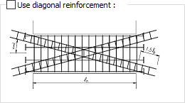
It is the option for reinforcing tie beams between rigid walls. When the option is selected, the reinforcement type given in TBDY 2018 Article 7.6.8.2 is applied. |
|
Design without bent up bars If the option is checked, the pillar design is not made on the beams. The beam is reinforced with upper and lower straight reinforcement. |
|
Two bent up bars If you want to break the double piles on the beam, this option should be marked by clicking. |
|
Bent up bar angle How many degrees to break the beam pile is entered. The moment is brought to zero point due to the column to the pillar and it is broken by the value written here. |
|
BU/Total min Determines the minimum percentage of the total area of reinforcement in the span in the beam to be arranged as pleats. This value is used in conjunction with the defined straight and pleat diameters in the reinforcement selection and the "minimum distance between two reinforcements", "reinforcement margin" and "combination range allowed to select reinforcement", which can be defined in the analysis settings. |
|
BU/Total max Determines the maximum percentage of the total area of reinforcement in the span in the beam to be arranged in piles. This value is used in conjunction with the "minimum distance between two rebars", "rebar margin" and "combination range allowed to select reinforcement", which can be defined in the analysis settings with the flat and pleat diameters defined in the reinforcement selection. |
|
Two stirrups Except for the stirrup condition that can be defined in the double beam parameters, double stirrups are marked by clicking if desired. |
|
All densified stirrups Stirrup tightening in beams is made according to earthquake regulations. According to the regulation, the densification zone is created at a distance of 2 times the beam depth from the column face. If this option is selected, complete stirrup tightening is performed on the beam regardless of the regulation conditions and beam length. |
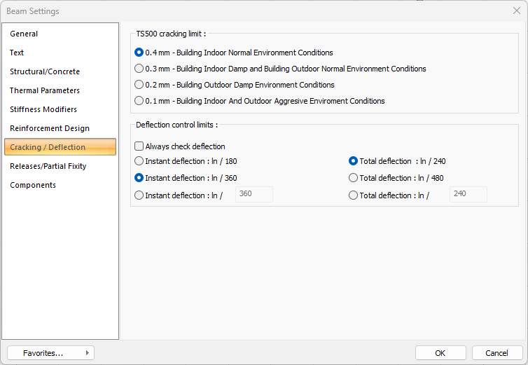
Cracking/Deflection Tab
|
Specifications |
|---|
|
Apply TBDY 3.2.3 (Automatic stiffness reduction forcoupling beams between shearwalls) When calculating according to TBDY 2007, section stiffnesses to be used in TBDY Article 3.2.3 "structural system calculation, section stiffnesses of the uncracked section will be used in the structural system calculation to be made with the methods given in Section 2. However, values of the cracked section can be used in beams that are stuck to the walls in their own planes and in the tie beams of the tie beam (hollow) walls. If this option is activated for beams connected from both sides in the plane of the wall based on the condition “, the moment of inertia of the beam is automatically reduced by 50%. |
|
TS500 cracking limit 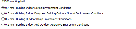
The upper limit to be considered for crack control of beam elements is determined by selecting the relevant option. The upper limit values are the values specified in TS500. |
|
Deflection control limits 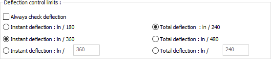
Deflection control upper limit values are determined from these options. Fixed values are taken from TS500 and you can also set limit values yourself. If "deflection control" option is selected, instantaneous and temporal deflection control is performed on the beams even if the "deflection condition is a height condition that does not require deflection control". |
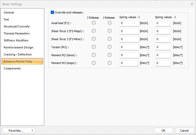
Releases/Partial Fixity Tab
|
Specifications |
|---|
|
Override end releases 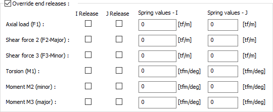
This tab is only visible when beams are selected and Object Properties and settings are called. It can be used to change the state of freedom / recess at the left and right ends of the beam. You can change these parameters, which do not need to intervene under normal circumstances, by marking the option in the relevant direction when you need them for the design in accordance with the regulation. i is the left end of the element, j is the right end of the element. The larger the spring value, the less displacement will be on the relevant tip. You can change the values of the parameter you want to change on the appropriate axis. |
Building Components
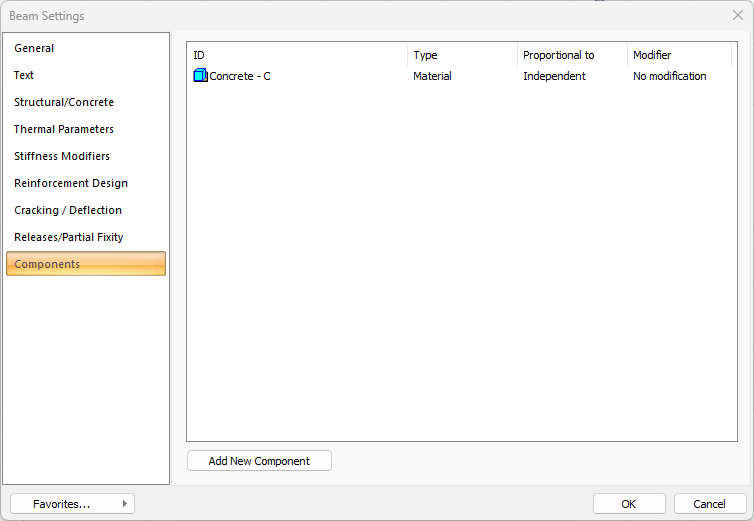
Add Building Components: Assigns the projected building materials to the object for detailed building components metrics.
-
Click on the building components button.
-
The Component Selection dialog will open.
-
In this dialog, click on the folder related to the material from the list on the left. Click on the material you want to use.
-
Set the parameters on the right.
-
Click the OK button. The "Component Selection" dialog will be closed. A summary line of the material will appear in the Building Components tab. More than one material assignment can be made to an object.
The parameters available in the component selection dialog are:
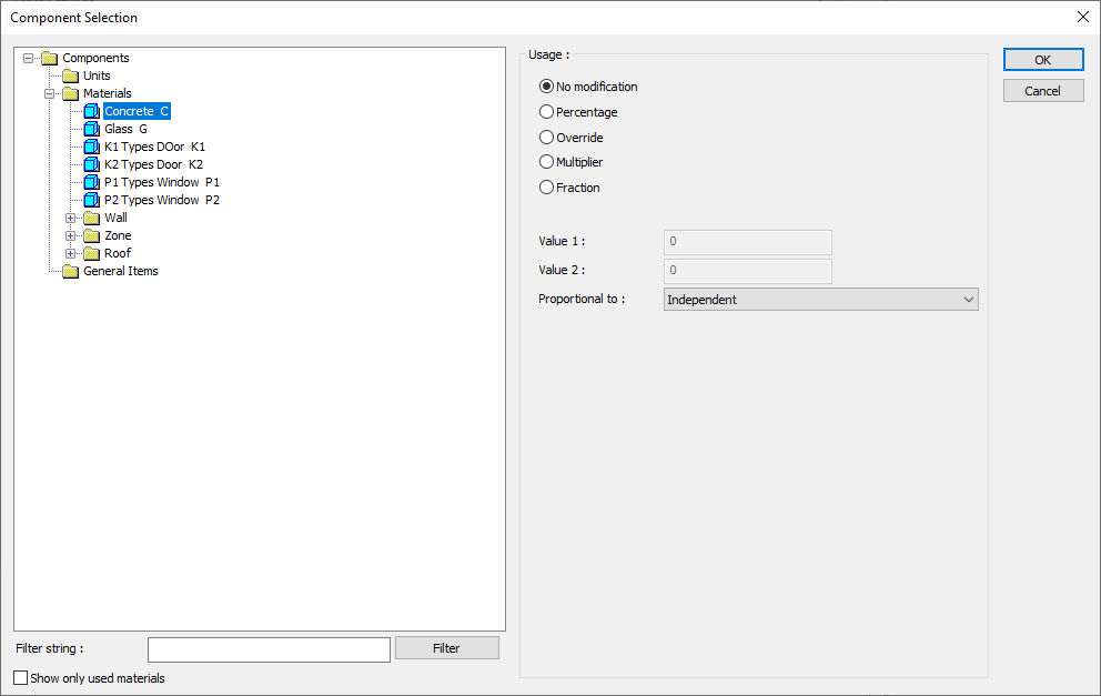
In the usage section
No modification: The amount of material to be assigned for the object in question is marked when it is desired to be used in the size that was previously specified in the material definition.
Percentage: This line is marked when it is desired to be used with the percentage of the amount previously determined in the material definition, as much as the value entered in the "Value 1" line in the same dialog. For example, if the material quantity is 70, if the line “Value 1” says 40, it means the material amount will be used up to 40 * 70%.
Override: This line is marked so that the quantity entered in the “Value 1” line in the same dialog will be used instead of the quantity previously determined in the material definition.
Multiplier: This line is marked in order to use the value found at the end of the multiplication of the value entered in the "Value 1" line in the same dialog with the amount previously determined in the material definition.
Fraction: This line is marked so that the amount determined in the material definition before will be used as the fraction value created by the values entered in the "Value 1" and "Value 2" lines in the same dialog. "Value 1" is the denominator "Value 2" is the denominator.
Proportional to: It is determined to what scale-area, circumference, length etc.-, region-side area, top, edge etc.- the material will be proportioned to. The content of the proportional list box is automatically determined according to the object and the size of the material. For example, a different list will be created if an operation is made for the column, a different list will be created for the library, a different list for the volume, and a different list for the field.
Following are the lines that appear in the proportion list according to the beam object and material size.
|
Beam |
||
|
Measure |
Listed |
Explanation |
|
Constant |
Independent |
The fixed measure used will be used exactly as the amount. |
|
Length |
Independent |
It means that the length measure found while defining the material will be used exactly as the length value. |
|
Front length |
It means that the length of the material will be found by multiplying the length of the front side of the beam with respect to the beam viewing direction. |
|
|
Back length |
It means that the length of the material will be found by multiplying the length of the length measured while defining the material and the length of the back side of the beam according to the viewing direction. |
|
|
Average length |
It means that the length of the material will be found by multiplying the length value found when defining the material and the average length value found from the length of the front and back sides of the beam. |
|
|
Average height |
It means that the length of the material will be found by multiplying the length value found by taking the average of the height of the left and right ends of the beam with the length measure found while defining the material. |
|
|
Thickness |
It means that the length of the material will be found by multiplying the length measure found when defining the material and the thickness of the beam. |
|
|
Area |
Independent |
It means that the area measure found while defining the material will be used exactly as the amount. |
|
Front area |
It means that the value to be found by multiplying the area measure found when defining the material with the area of the front surface according to the beam's viewing direction will be used as the material area. |
|
|
Back area |
It means that the value to be found by multiplying the area measure found while defining the material with the area of the surface on the back with respect to the beam's viewing direction will be used as the material area. |
|
|
Front and back area |
The value found by multiplying the area measure found when defining the material and the sum of the front and back areas of the beam will be used as the material area. |
|
|
Start area |
The value to be found by multiplying the area measure found while defining the material and the area of the surface on the left according to the beam's viewing direction will be used as the material area. |
|
|
End area |
The value to be found by multiplying the area measure found while defining the material and the area of the surface on the right according to the beam's viewing direction, means to be used as the material area. |
|
|
Start and end area |
When defining the material, the value found by multiplying the sum of the area measure found on the left and right sides of the beam with the surface area on the left and right means the material area will be used. |
|
|
Top area |
The value to be found by multiplying the area measure found when defining the material with the area of the surface remaining on the beam, means to be used as the material area. |
|
|
Bottom area |
The value to be found by multiplying the area of the area found when defining the material and the area of the surface under the beam means to be used as the material area. |
|
|
Top and bottom area |
The value found by multiplying the sum of the area measure found while defining the material and the surface areas on the upper and lower sides of the beam will be used as the material area. |
|
|
Side area |
The total value found by multiplying each of the surfaces on the sides of the beam with the area measure found when defining the material means to be used as the material area. |
|
|
Volume |
Independent |
It means that the volume measurement found when defining the material will be used exactly as the volume value. |
|
Volume |
It means that the volume measure found when defining the material will be used by multiplying the beam volume. |
|
|
Count |
Independent |
The number measure found while defining the material will be used exactly as the material number. |
|
Count |
The number measure found while defining the material will be used exactly as the material number. |
|
Next Topic