
ICONS
DTS = Earthquake Design Class
fctd = Design tensile strength of concrete
fyd = Design yield strength of longitudinal reinforcement
lb = Interlock length given for tensile reinforcement at TS 500
ρ = ratio of upper or lower tensile reinforcement in beam support
ϕ = Reinforcement diameter
7.4.2. Longitudinal Reinforcement Conditions
7.4.2.1 - The requirement given by Equation (7.8) shall be complied with for the minimum ratio of tensile reinforcement in beam supports .

7.4.2.2 - Diameter of longitudinal reinforcement shall not be less than 12 mm. At least two reinforcing bars at the top and bottom of the beam shall be located continuously along the beam span.
7.4.2.3 - Earthquake Design Class; In carrier systems with DTS = 1, 1a and DTS = 2, 2a, the lower reinforcement on the beam support cannot be less than 50% of the upper reinforcement on the same support. However, in other cases this rate can be reduced to 30%.
7.4.3. Arrangement of Longitudinal Reinforcement
7.4.3.1 - placing and conditions of engagement of the longitudinal reinforcement (a) , (b) and (c) is given in (Figure 7.7) :
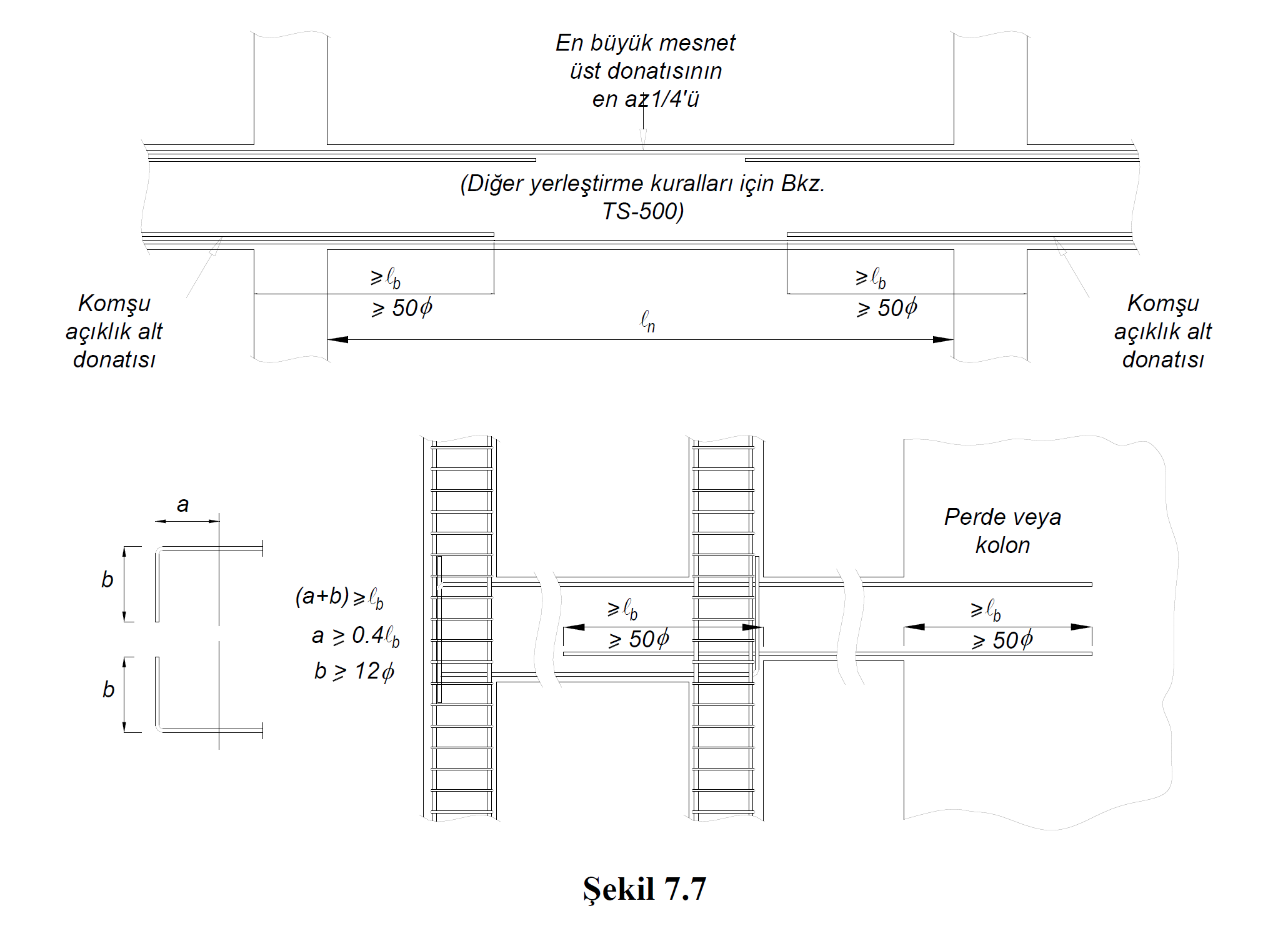
(a) At least 1/4 of the larger of the support top reinforcements at both ends of the beam will be continued continuously along the whole beam. The remaining part of the support upper reinforcement shall be arranged in accordance with TS 500 so that no unmet moment is left along the beam.
(b) In cases where the beams joining the column do not continue on the other side of the column, the upper and lower reinforcement of the beams shall be extended to the opposite surface of the core of the column wrapped with stirrups and bent 90 degrees from the inside of the stirrups. In this case the total length of the horizontal part of the remaining 90 degree bent vertical part of longitudinal reinforcement inside the column specified in TS 500 straight development length l b 'will be less than. The horizontal part of the 90 degree hook shall not be less than 0.4l b and the vertical part shall not be less than 12ϕ. Straight development length dimension of the curtain and α l b from 50φ and from the columns in excess, the engagement of the longitudinal reinforcement may be provided as flat without 90 degree hook.
(c) In case of joining of beams to columns from both sides, beam bottom reinforcements shall be extended from the face of the column adjacent to the span, by not less than 50ϕ, at least by the clamping length given in TS 500 by 1 b . In cases where this possibility is not available for reasons such as height difference in beams, clamping shall be done as described in paragraph (b) above for cases where the beam does not continue on the other side of the column.
7.4.3.2 - Conditions for the attachment of longitudinal reinforcement are given in (a) and (b) below :
(a) 7.4.4. No lap splices shall be made in critical areas where the reinforcement is likely to reach the creep state, such as the beam confinement zones, column-beam joints and lower reinforcement areas in the middle of the span. In places other than these regions where lap splices are to be made, special seismic hoops defined in 7.2.8 will be used throughout the appendix . The spacing of these stirrups shall not exceed 1/4 of the beam height and 100 mm. There is no need to use special earthquake hoops in the joints of the upper mounting reinforcement outside the confinement zones in the opening.
(b) Sleeved splices or lap welded joints shall be applied in one section by skipping only one reinforcement and the longitudinal distance between the centers of two adjacent splices shall not be less than 600 mm.
Next Topic