
With the wall command, sketches of architectural design are drawn and easily transferred to ideCAD, and walls are modeled. While the walls are being drawn, a building information model is formed at the same time.
Location of Wall Command
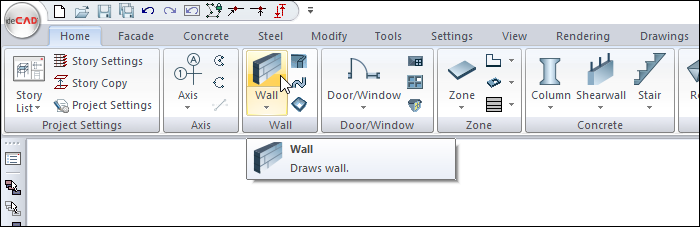
In Architectural Program
You can access it under the ribbon menu Home tab, Wall title.
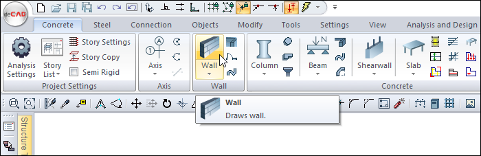
In Structural Program
You can reach it under the ribbon menu Concrete tab, Wall title.
Usage Steps
-
Click the Wall icon from the ribbon menu. The wall toolbar will open.
-
From the drawing area, move your mouse to the point where you want your wall to begin and click the left button.
-
The starting point of your wall will be defined and the preview will appear on the screen. It will move on your wall with the movement of your mouse.
-
You can draw a straight or perpendicular edge by pressing the shift key on the keyboard.
-
You can define your wall by holding different points (bottom corner, middle or top corner) by clicking the delta icon from the wall toolbar or by pressing the spacebar on the keyboard. Every time you press the spacebar, your alignment will change.
-
Click the left mouse button on any point of the drawing area again to determine the second point of the wall. The ideCAD will create a preview of your next wall.
-
Press esc to exit the command. Your wall will be formed.
You can determine the second point of your wall by entering length and angle. For this;
-
Determine the first point of the wall.
-
After determining the first point of the wall , press the A key on the keyboard to enter an angle . The cursor will go to the A digit in the coordinate box . Enter 90 (degrees) here as the angle value and press enter. The direction of the wall being drawn will be locked to the entered angle value.
-
To enter the length , press the L key on the keyboard . The cursor will go to the L digit in the coordinate box . Enter here 350 (cm) as the length value and press enter. The wall being drawn will be limited by the length value.
-
A wall preview will be created in the direction and length of the angle you entered in the drawing area.
-
When you click the left mouse button, the second point of your wall will be determined. The ideCAD will create a preview of your next wall.
-
Press esc to exit the command. Your wall will be formed.
|
Usage step |
|---|
|
Determining the starting point of the wall in the drawing area 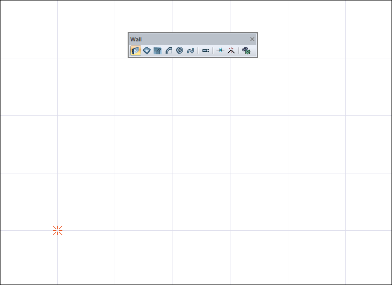
|
|
Creating the starting point by clicking the left mouse button 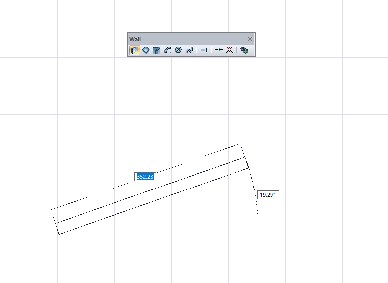
|
|
Drawing a straight or vertical edge by pressing the shift key on the keyboard 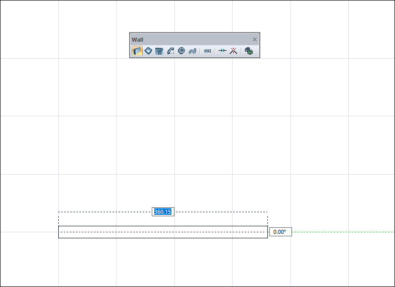
|
|
Changing the wall delta by pressing the spacebar 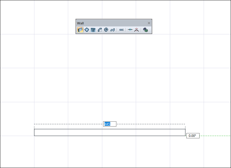
|
|
Creating the second point of the wall by clicking the left mouse button 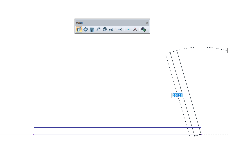
|
|
Exiting the command by pressing the Esc key on the keyboard and creating a wall 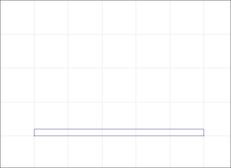
|
|
Determining the first point for the second wall 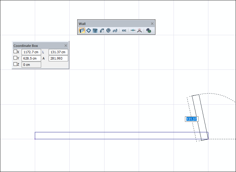
|
|
For the direction of the wall, press the A key on the keyboard, enter the value 90 and lock the angle by pressing the Enter key. 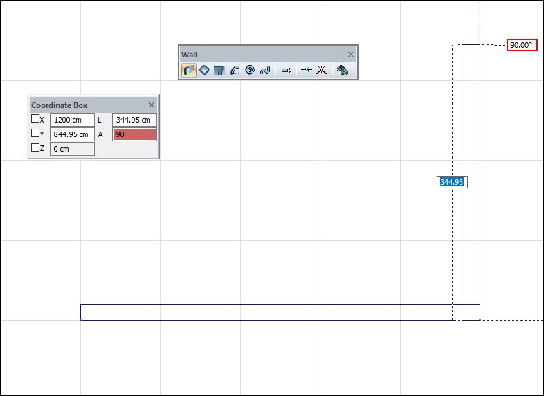
|
|
For the length of the wall, press the L key on the keyboard and enter the value 350 and lock the length by pressing the Enter key. 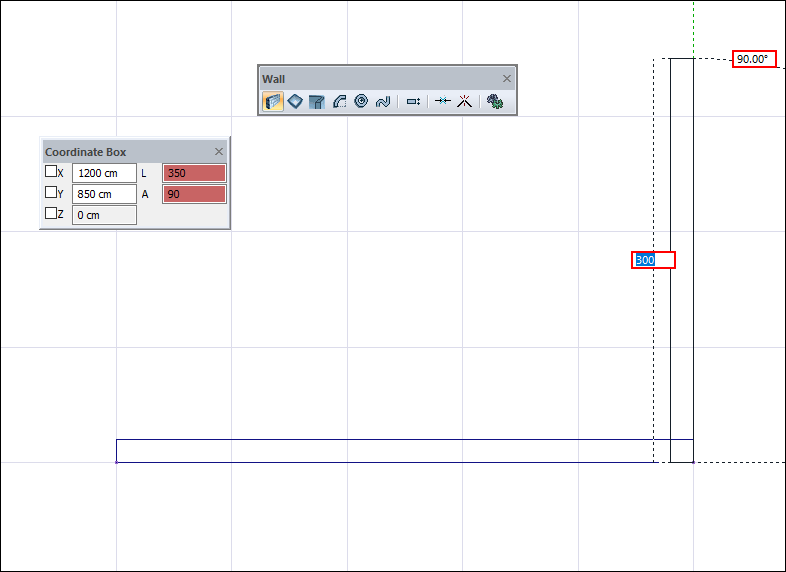
|
|
Creating the second point of the wall by clicking the left mouse button 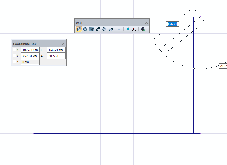
|
|
Exiting the command by pressing the Esc key on the keyboard and creating a wall 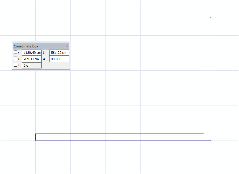
|
Next Topic