
How does ideCAD design moment connections according to AISC 358-16 and AISC 360-16?
-
Limit states of moment connections are calculated automatically according to AISC 358-16 and AISC 360-16.
Symbols
Cpr: Stiffening in the joint, etc., a coefficient that takes into account the circumstances and is used to calculate the maximum possible bending moment strength
Fu: Structural steel characteristic tensile strength
Fy: Characteristic yield stress in structural steel
lh: The distance of possible plastic hinge point at the beam ends to the column face
ln: Beam span between possible plastic hinge points at the beam ends
Mpr: Possible bending moment capacity
Mpri: Possible bending moment capacity at the left end i of the beam
Mprj: Possible bending moment capacity at the right end j of the beam
Muc: Required bending moment strength of the joint at the face of the column
Ry: ratio of possible yield stress to characteristic yield stress
Vd: Simple beam shear force arising from vertical loads at the plastic hinge point of the beam.
Vuc: Required shear strength of the joint at the face of the column
General Provisions
Moment connections are designed to have sufficient stiffness to transfer the combined effect of forces resulting from moment and shear. Moment connections are rigid and full/partial restrained joints.
Rigid connections, end plates, bolted flange plates, and welded moment connections are classified according to rotational rigidity, and rotational stiffness ratios are defined in the earthquake code depending on the ductility level.
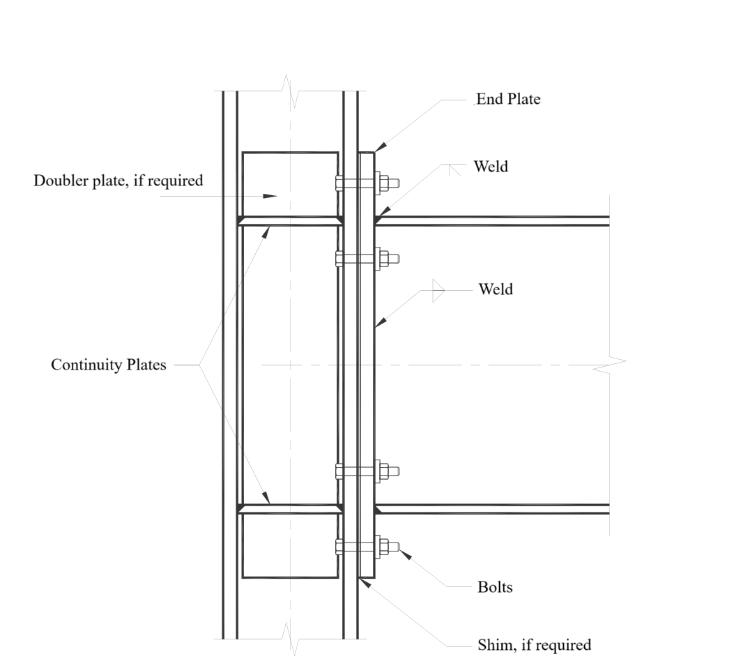
General Design Rules for End Plate Connections
End-plate connections consist of welding the beam to an end-plate and bolting the end-plate to a column flange.
Limit states of end-plate moment connections are flexural yielding of the beam section, flexural yielding of the end-plates, yielding of the column panel zone, tension rupture of the end-plate bolts, shear rupture of the end-plate bolts, or rupture of various welded joints.
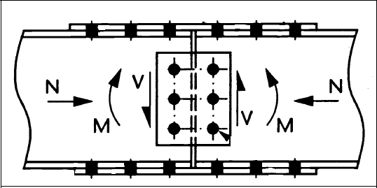
If there is no axial load on the connection, total tensile and compressive forces are equal and opposite in both flanges, so that total force creates a force pair. It is accepted that the center of rotation is in the center of the compression flange.
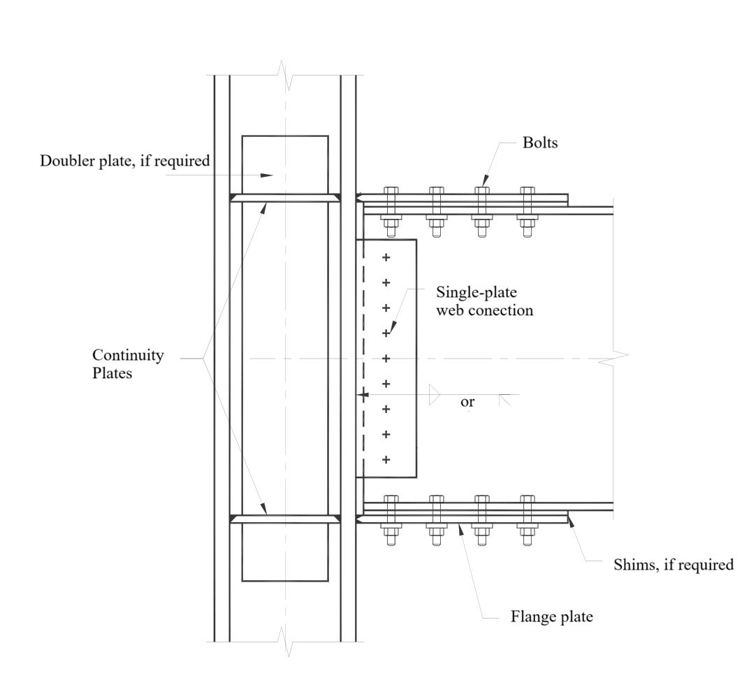
General Design Rules for Flange Plate Connections
Bolted flange plate moment connections consist of plates welded to column flanges and bolted to beam flanges. The top and bottom plates must be identical to be suitable for design with reversible forces such as seismic forces.
Bolted flange plate connections are formed by welding with CJP groove welds to the column flange and bolted to the beam flange. The beam web is connected to the column flange using a bolted shear tab with bolts in short-slotted holes.
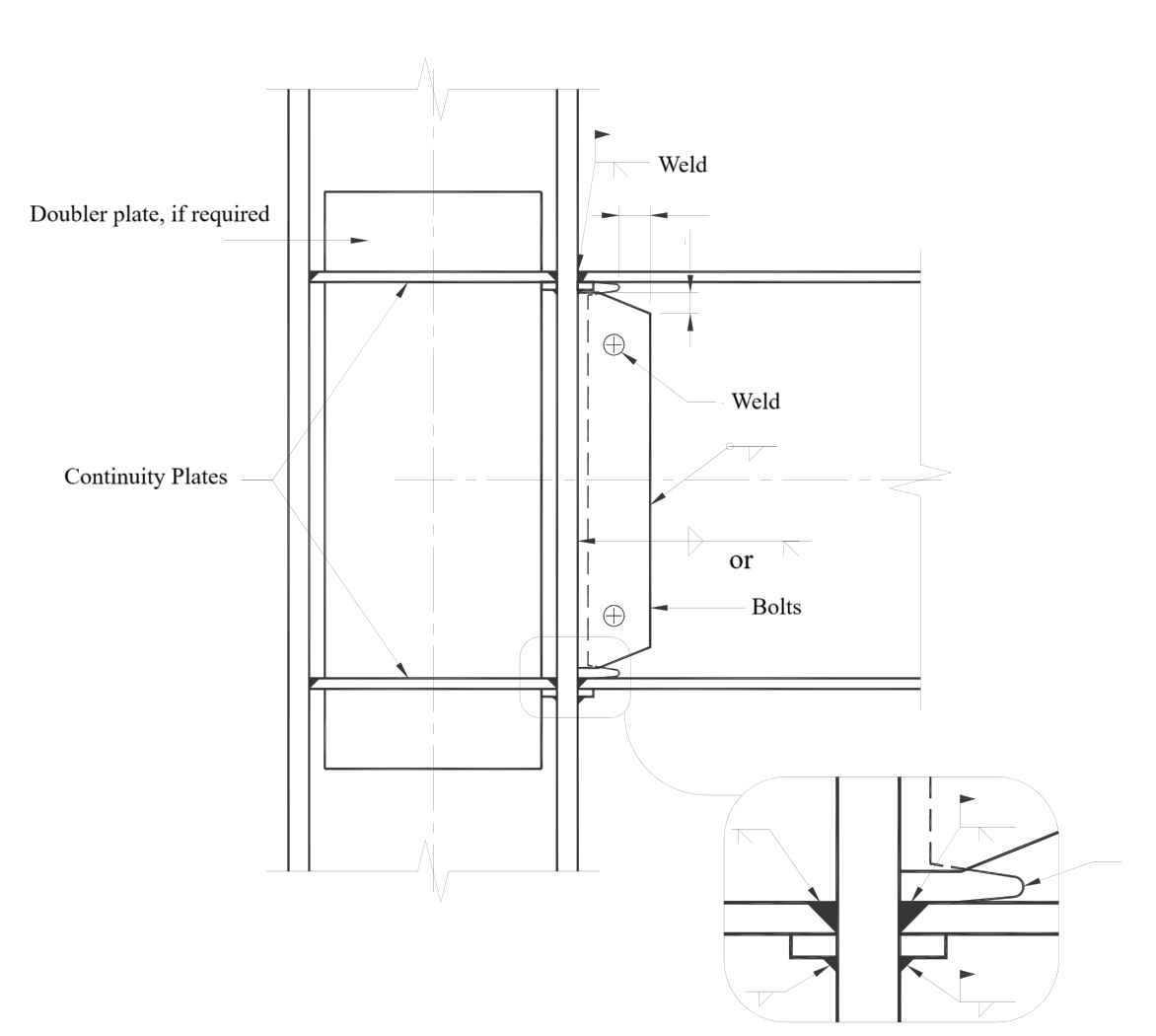
General Design Rules for Welded Web Connections
The welded web moment connection consists of welds joining the beam flanges to the column flange, the welds joining the beam web to the column flange, and the shape and finish of the weld access holes.
Column/Beam Splice Connections Design Rules
Asymmetrical and equal numbers of bolts are used on both flanges and the web to be suitable for design with reversible forces such as seismic forces. ideCAD Structural does not allow asymmetrical structure during modeling.
While it is assumed that flanges transfer the moment effect and web plates transfer the shear effect, the axial force is equally shared between both flanges.
AISC 358-16 Design Criteria
Depending on the ductility level, the connections that are determined to provide a relative angle of translation of at least 0.04 or 0.02 radians should be used. End plate joints and flange plate joints are designed in ideCAD Structural.
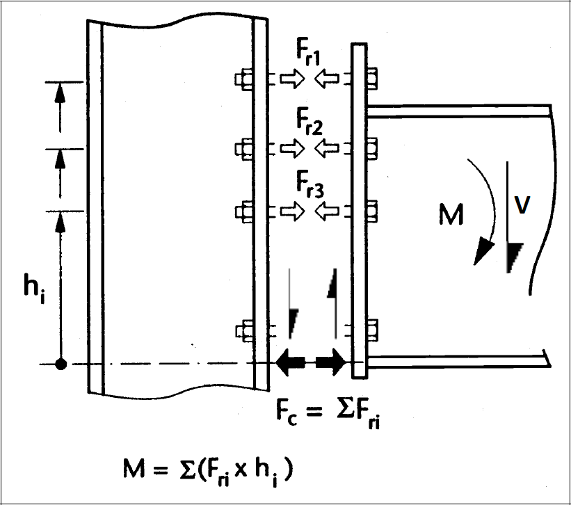
The required bending moment strength Mu and the required shear strength Vu on the column face of the joints are calculated over the plastic joints at the end of the beam. The formulas in the image below are used in the design.
The probable maximum moment at the plastic hinge is given below, according to AISC 358-16.
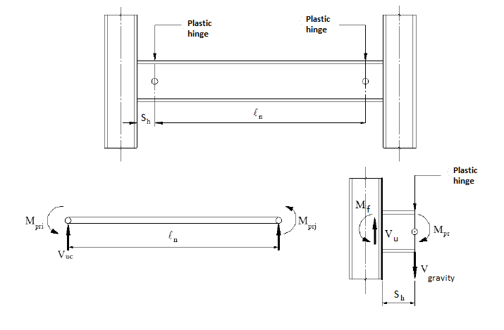
The moment at the face of the column, Mf., is calculated according to AISC 358-16 Eq. 6.8-1 given below.
The Vu used in the dimensioning of the joint is determined according to the equation in the above image by summing the shear force determined based on the yield state and the shear force calculated from the combination of 1.2G + 0.5Q + 0.2S on the plastic joint at the end of the beam.
Plastic hinge length is specified separately for each joint in AISC 341-16, and these rules make automatic calculations. Details will be given in each respective combination.
The shear strength required for the shear zone is calculated using the column shear force generated by possible plastic moments of beams connecting to the column.