
Steel Columns subject to axial force and flexure about both axes design are explained in detail under this title.
Symbols
Pr = required axial strength determined using LRFD or ASD load combinations, kips (N)
Pc = available axial strength, kips (N)
Mr = required flexural strength, determined using LRFD or ASD load combinations, kip-in. (N-mm)
Mc = available flexural strength, kip- in. (N-mm)
Design for Axial Force and Flexural Moment
-
The strength calculation considers the combined stresses created in the elements under flexural and axial force.
-
The superposition of the stresses only applies to similar stresses.
-
The superposition rule does not apply to stability losses.
Design with AISC 360-16
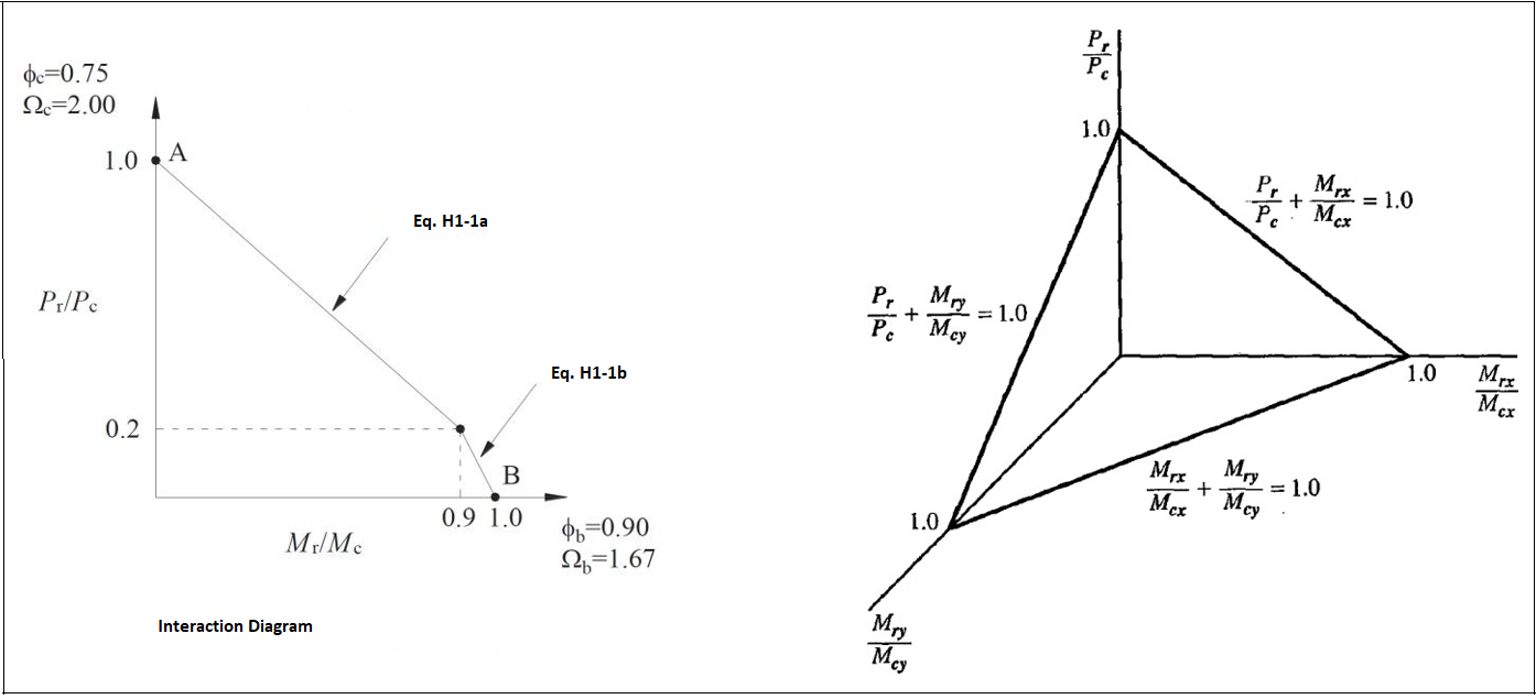
Equation H1.1 is used for biaxial and single symmetry axis members under the influence of axial compression and flexural moment.
'%3e%3cg transform='translate(167%2c0)'%3e%3cg transform='translate(-13%2c0)'%3e%3cg transform='translate(0%2c-12)'%3e%3cuse xlink:href='%23MJMAIN-57' x='0' y='0'%3e%3c/use%3e%3cuse xlink:href='%23MJMAIN-68' x='1028' y='0'%3e%3c/use%3e%3cuse xlink:href='%23MJMAIN-65' x='1585' y='0'%3e%3c/use%3e%3cuse xlink:href='%23MJMAIN-6E' x='2029' y='0'%3e%3c/use%3e%3cg transform='translate(3141%2c0)'%3e%3cg transform='translate(120%2c0)'%3e%3crect stroke='none' width='1181' height='60' x='0' y='220'%3e%3c/rect%3e%3cg transform='translate(60%2c676)'%3e%3cuse xlink:href='%23MJMATHI-50' x='0' y='0'%3e%3c/use%3e%3cuse transform='scale(0.707)' xlink:href='%23MJMATHI-72' x='908' y='-213'%3e%3c/use%3e%3c/g%3e%3cg transform='translate(66%2c-686)'%3e%3cuse xlink:href='%23MJMATHI-50' x='0' y='0'%3e%3c/use%3e%3cuse transform='scale(0.707)' xlink:href='%23MJMATHI-63' x='908' y='-213'%3e%3c/use%3e%3c/g%3e%3c/g%3e%3c/g%3e%3cuse xlink:href='%23MJMAIN-2265' x='4841' y='0'%3e%3c/use%3e%3cg transform='translate(5897%2c0)'%3e%3cuse xlink:href='%23MJMAIN-30'%3e%3c/use%3e%3cuse xlink:href='%23MJMAIN-2E' x='500' y='0'%3e%3c/use%3e%3cuse xlink:href='%23MJMAIN-32' x='779' y='0'%3e%3c/use%3e%3c/g%3e%3cg transform='translate(10232%2c0)'%3e%3cg transform='translate(120%2c0)'%3e%3crect stroke='none' width='1181' height='60' x='0' y='220'%3e%3c/rect%3e%3cg transform='translate(60%2c676)'%3e%3cuse xlink:href='%23MJMATHI-50' x='0' y='0'%3e%3c/use%3e%3cuse transform='scale(0.707)' xlink:href='%23MJMATHI-72' x='908' y='-213'%3e%3c/use%3e%3c/g%3e%3cg transform='translate(66%2c-686)'%3e%3cuse xlink:href='%23MJMATHI-50' x='0' y='0'%3e%3c/use%3e%3cuse transform='scale(0.707)' xlink:href='%23MJMATHI-63' x='908' y='-213'%3e%3c/use%3e%3c/g%3e%3c/g%3e%3c/g%3e%3cuse xlink:href='%23MJMAIN-2B' x='11876' y='0'%3e%3c/use%3e%3cg transform='translate(12877%2c0)'%3e%3cg transform='translate(120%2c0)'%3e%3crect stroke='none' width='620' height='60' x='0' y='220'%3e%3c/rect%3e%3cuse xlink:href='%23MJMAIN-38' x='60' y='676'%3e%3c/use%3e%3cuse xlink:href='%23MJMAIN-39' x='60' y='-686'%3e%3c/use%3e%3c/g%3e%3c/g%3e%3cuse xlink:href='%23MJSZ3-28' x='13737' y='-1'%3e%3c/use%3e%3cg transform='translate(14474%2c0)'%3e%3cg transform='translate(120%2c0)'%3e%3crect stroke='none' width='1914' height='60' x='0' y='220'%3e%3c/rect%3e%3cg transform='translate(60%2c676)'%3e%3cuse xlink:href='%23MJMATHI-4D' x='0' y='0'%3e%3c/use%3e%3cg transform='translate(970%2c-150)'%3e%3cuse transform='scale(0.707)' xlink:href='%23MJMATHI-72' x='0' y='0'%3e%3c/use%3e%3cuse transform='scale(0.707)' xlink:href='%23MJMATHI-78' x='451' y='0'%3e%3c/use%3e%3c/g%3e%3c/g%3e%3cg transform='translate(66%2c-686)'%3e%3cuse xlink:href='%23MJMATHI-4D' x='0' y='0'%3e%3c/use%3e%3cg transform='translate(970%2c-150)'%3e%3cuse transform='scale(0.707)' xlink:href='%23MJMATHI-63' x='0' y='0'%3e%3c/use%3e%3cuse transform='scale(0.707)' xlink:href='%23MJMATHI-78' x='433' y='0'%3e%3c/use%3e%3c/g%3e%3c/g%3e%3c/g%3e%3c/g%3e%3cuse xlink:href='%23MJMAIN-2B' x='16850' y='0'%3e%3c/use%3e%3cg transform='translate(17851%2c0)'%3e%3cg transform='translate(120%2c0)'%3e%3crect stroke='none' width='1901' height='60' x='0' y='220'%3e%3c/rect%3e%3cg transform='translate(80%2c789)'%3e%3cuse xlink:href='%23MJMATHI-4D' x='0' y='0'%3e%3c/use%3e%3cg transform='translate(970%2c-150)'%3e%3cuse transform='scale(0.707)' xlink:href='%23MJMATHI-72' x='0' y='0'%3e%3c/use%3e%3cuse transform='scale(0.707)' xlink:href='%23MJMATHI-79' x='451' y='0'%3e%3c/use%3e%3c/g%3e%3c/g%3e%3cg transform='translate(60%2c-686)'%3e%3cuse xlink:href='%23MJMATHI-4D' x='0' y='0'%3e%3c/use%3e%3cg transform='translate(970%2c-150)'%3e%3cuse transform='scale(0.707)' xlink:href='%23MJMATHI-63' x='0' y='0'%3e%3c/use%3e%3cuse transform='scale(0.707)' xlink:href='%23MJMATHI-78' x='433' y='0'%3e%3c/use%3e%3c/g%3e%3c/g%3e%3c/g%3e%3c/g%3e%3cuse xlink:href='%23MJSZ3-29' x='19993' y='-1'%3e%3c/use%3e%3cuse xlink:href='%23MJMAIN-2264' x='21007' y='0'%3e%3c/use%3e%3cg transform='translate(22064%2c0)'%3e%3cuse xlink:href='%23MJMAIN-31'%3e%3c/use%3e%3cuse xlink:href='%23MJMAIN-2E' x='500' y='0'%3e%3c/use%3e%3cuse xlink:href='%23MJMAIN-30' x='779' y='0'%3e%3c/use%3e%3c/g%3e%3cuse xlink:href='%23MJMAIN-28' x='31121' y='0'%3e%3c/use%3e%3cuse xlink:href='%23MJMATHI-48' x='31510' y='0'%3e%3c/use%3e%3cuse xlink:href='%23MJMAIN-31' x='32399' y='0'%3e%3c/use%3e%3cuse xlink:href='%23MJMAIN-2212' x='33122' y='0'%3e%3c/use%3e%3cuse xlink:href='%23MJMAIN-31' x='34122' y='0'%3e%3c/use%3e%3cuse xlink:href='%23MJMATHI-61' x='34623' y='0'%3e%3c/use%3e%3cuse xlink:href='%23MJMAIN-29' x='35152' y='0'%3e%3c/use%3e%3c/g%3e%3c/g%3e%3c/g%3e%3c/g%3e%3c/svg%3e)
'%3e%3cg transform='translate(167%2c0)'%3e%3cg transform='translate(-13%2c0)'%3e%3cg transform='translate(0%2c-12)'%3e%3cuse xlink:href='%23MJMAIN-57' x='0' y='0'%3e%3c/use%3e%3cuse xlink:href='%23MJMAIN-68' x='1028' y='0'%3e%3c/use%3e%3cuse xlink:href='%23MJMAIN-65' x='1585' y='0'%3e%3c/use%3e%3cuse xlink:href='%23MJMAIN-6E' x='2029' y='0'%3e%3c/use%3e%3cg transform='translate(3141%2c0)'%3e%3cg transform='translate(120%2c0)'%3e%3crect stroke='none' width='1181' height='60' x='0' y='220'%3e%3c/rect%3e%3cg transform='translate(60%2c676)'%3e%3cuse xlink:href='%23MJMATHI-50' x='0' y='0'%3e%3c/use%3e%3cuse transform='scale(0.707)' xlink:href='%23MJMATHI-72' x='908' y='-213'%3e%3c/use%3e%3c/g%3e%3cg transform='translate(66%2c-686)'%3e%3cuse xlink:href='%23MJMATHI-50' x='0' y='0'%3e%3c/use%3e%3cuse transform='scale(0.707)' xlink:href='%23MJMATHI-63' x='908' y='-213'%3e%3c/use%3e%3c/g%3e%3c/g%3e%3c/g%3e%3cuse xlink:href='%23MJMAIN-2265' x='4841' y='0'%3e%3c/use%3e%3cg transform='translate(5897%2c0)'%3e%3cuse xlink:href='%23MJMAIN-30'%3e%3c/use%3e%3cuse xlink:href='%23MJMAIN-2E' x='500' y='0'%3e%3c/use%3e%3cuse xlink:href='%23MJMAIN-32' x='779' y='0'%3e%3c/use%3e%3c/g%3e%3cg transform='translate(10232%2c0)'%3e%3cg transform='translate(120%2c0)'%3e%3crect stroke='none' width='1669' height='60' x='0' y='220'%3e%3c/rect%3e%3cg transform='translate(303%2c676)'%3e%3cuse xlink:href='%23MJMATHI-50' x='0' y='0'%3e%3c/use%3e%3cuse transform='scale(0.707)' xlink:href='%23MJMATHI-72' x='908' y='-213'%3e%3c/use%3e%3c/g%3e%3cg transform='translate(60%2c-686)'%3e%3cuse xlink:href='%23MJMAIN-32' x='0' y='0'%3e%3c/use%3e%3cg transform='translate(500%2c0)'%3e%3cuse xlink:href='%23MJMATHI-50' x='0' y='0'%3e%3c/use%3e%3cuse transform='scale(0.707)' xlink:href='%23MJMATHI-63' x='908' y='-213'%3e%3c/use%3e%3c/g%3e%3c/g%3e%3c/g%3e%3c/g%3e%3cuse xlink:href='%23MJMAIN-2B' x='12364' y='0'%3e%3c/use%3e%3cuse xlink:href='%23MJSZ3-28' x='13364' y='-1'%3e%3c/use%3e%3cg transform='translate(14101%2c0)'%3e%3cg transform='translate(120%2c0)'%3e%3crect stroke='none' width='1914' height='60' x='0' y='220'%3e%3c/rect%3e%3cg transform='translate(60%2c676)'%3e%3cuse xlink:href='%23MJMATHI-4D' x='0' y='0'%3e%3c/use%3e%3cg transform='translate(970%2c-150)'%3e%3cuse transform='scale(0.707)' xlink:href='%23MJMATHI-72' x='0' y='0'%3e%3c/use%3e%3cuse transform='scale(0.707)' xlink:href='%23MJMATHI-78' x='451' y='0'%3e%3c/use%3e%3c/g%3e%3c/g%3e%3cg transform='translate(66%2c-686)'%3e%3cuse xlink:href='%23MJMATHI-4D' x='0' y='0'%3e%3c/use%3e%3cg transform='translate(970%2c-150)'%3e%3cuse transform='scale(0.707)' xlink:href='%23MJMATHI-63' x='0' y='0'%3e%3c/use%3e%3cuse transform='scale(0.707)' xlink:href='%23MJMATHI-78' x='433' y='0'%3e%3c/use%3e%3c/g%3e%3c/g%3e%3c/g%3e%3c/g%3e%3cuse xlink:href='%23MJMAIN-2B' x='16478' y='0'%3e%3c/use%3e%3cg transform='translate(17478%2c0)'%3e%3cg transform='translate(120%2c0)'%3e%3crect stroke='none' width='1901' height='60' x='0' y='220'%3e%3c/rect%3e%3cg transform='translate(80%2c789)'%3e%3cuse xlink:href='%23MJMATHI-4D' x='0' y='0'%3e%3c/use%3e%3cg transform='translate(970%2c-150)'%3e%3cuse transform='scale(0.707)' xlink:href='%23MJMATHI-72' x='0' y='0'%3e%3c/use%3e%3cuse transform='scale(0.707)' xlink:href='%23MJMATHI-79' x='451' y='0'%3e%3c/use%3e%3c/g%3e%3c/g%3e%3cg transform='translate(60%2c-686)'%3e%3cuse xlink:href='%23MJMATHI-4D' x='0' y='0'%3e%3c/use%3e%3cg transform='translate(970%2c-150)'%3e%3cuse transform='scale(0.707)' xlink:href='%23MJMATHI-63' x='0' y='0'%3e%3c/use%3e%3cuse transform='scale(0.707)' xlink:href='%23MJMATHI-78' x='433' y='0'%3e%3c/use%3e%3c/g%3e%3c/g%3e%3c/g%3e%3c/g%3e%3cuse xlink:href='%23MJSZ3-29' x='19620' y='-1'%3e%3c/use%3e%3cuse xlink:href='%23MJMAIN-2264' x='20635' y='0'%3e%3c/use%3e%3cg transform='translate(21691%2c0)'%3e%3cuse xlink:href='%23MJMAIN-31'%3e%3c/use%3e%3cuse xlink:href='%23MJMAIN-2E' x='500' y='0'%3e%3c/use%3e%3cuse xlink:href='%23MJMAIN-30' x='779' y='0'%3e%3c/use%3e%3c/g%3e%3cuse xlink:href='%23MJMAIN-28' x='30748' y='0'%3e%3c/use%3e%3cuse xlink:href='%23MJMATHI-48' x='31138' y='0'%3e%3c/use%3e%3cuse xlink:href='%23MJMAIN-31' x='32026' y='0'%3e%3c/use%3e%3cuse xlink:href='%23MJMAIN-2212' x='32749' y='0'%3e%3c/use%3e%3cuse xlink:href='%23MJMAIN-31' x='33750' y='0'%3e%3c/use%3e%3cuse xlink:href='%23MJMATHI-62' x='34250' y='0'%3e%3c/use%3e%3cuse xlink:href='%23MJMAIN-29' x='34680' y='0'%3e%3c/use%3e%3c/g%3e%3c/g%3e%3c/g%3e%3c/g%3e%3c/svg%3e)
Flexural design is explained under the title of Design of Steel Members for Flexure per AISC 360-16 §F
Compression design is explained under the title of Design of Steel Members for Compression per AISC 360-16 §E
-
Design axial strength,
![]() (LRFD)
(LRFD) -
Allowable axial strength
![]() (ASD)
(ASD) -
Design flexural strength,
![]() (LRFD)
(LRFD) -
Allowable flexural strength
![]() (ASD)
(ASD)
'%3e%3cg transform='translate(167%2c0)'%3e%3cg transform='translate(-13%2c0)'%3e%3cg transform='translate(0%2c-47)'%3e%3cuse xlink:href='%23MJMATHI-50' x='0' y='0'%3e%3c/use%3e%3cuse transform='scale(0.707)' xlink:href='%23MJMATHI-63' x='908' y='-213'%3e%3c/use%3e%3cuse xlink:href='%23MJMAIN-3D' x='1326' y='0'%3e%3c/use%3e%3cg transform='translate(2383%2c0)'%3e%3cuse xlink:href='%23MJMATHI-3D5' x='0' y='0'%3e%3c/use%3e%3cuse transform='scale(0.707)' xlink:href='%23MJMATHI-63' x='843' y='-213'%3e%3c/use%3e%3c/g%3e%3cg transform='translate(3386%2c0)'%3e%3cuse xlink:href='%23MJMATHI-50' x='0' y='0'%3e%3c/use%3e%3cuse transform='scale(0.707)' xlink:href='%23MJMATHI-6E' x='908' y='-213'%3e%3c/use%3e%3c/g%3e%3c/g%3e%3c/g%3e%3c/g%3e%3c/g%3e%3c/svg%3e)
'%3e%3cg transform='translate(167%2c0)'%3e%3cg transform='translate(-13%2c0)'%3e%3cg transform='translate(0%2c-25)'%3e%3cuse xlink:href='%23MJMATHI-50' x='0' y='0'%3e%3c/use%3e%3cuse transform='scale(0.707)' xlink:href='%23MJMATHI-63' x='908' y='-213'%3e%3c/use%3e%3cuse xlink:href='%23MJMAIN-3D' x='1326' y='0'%3e%3c/use%3e%3cg transform='translate(2383%2c0)'%3e%3cuse xlink:href='%23MJMATHI-50' x='0' y='0'%3e%3c/use%3e%3cuse transform='scale(0.707)' xlink:href='%23MJMATHI-6E' x='908' y='-213'%3e%3c/use%3e%3c/g%3e%3cuse xlink:href='%23MJMAIN-2F' x='3550' y='0'%3e%3c/use%3e%3cg transform='translate(4050%2c0)'%3e%3cuse xlink:href='%23MJMAIN-3A9' x='0' y='0'%3e%3c/use%3e%3cuse transform='scale(0.707)' xlink:href='%23MJMATHI-63' x='1021' y='-213'%3e%3c/use%3e%3c/g%3e%3c/g%3e%3c/g%3e%3c/g%3e%3c/g%3e%3c/svg%3e)
'%3e%3cg transform='translate(167%2c0)'%3e%3cg transform='translate(-13%2c0)'%3e%3cg transform='translate(0%2c-47)'%3e%3cuse xlink:href='%23MJMATHI-4D' x='0' y='0'%3e%3c/use%3e%3cuse transform='scale(0.707)' xlink:href='%23MJMATHI-63' x='1372' y='-213'%3e%3c/use%3e%3cuse xlink:href='%23MJMAIN-3D' x='1654' y='0'%3e%3c/use%3e%3cg transform='translate(2711%2c0)'%3e%3cuse xlink:href='%23MJMATHI-3D5' x='0' y='0'%3e%3c/use%3e%3cuse transform='scale(0.707)' xlink:href='%23MJMATHI-62' x='843' y='-213'%3e%3c/use%3e%3c/g%3e%3cg transform='translate(3711%2c0)'%3e%3cuse xlink:href='%23MJMATHI-4D' x='0' y='0'%3e%3c/use%3e%3cuse transform='scale(0.707)' xlink:href='%23MJMATHI-6E' x='1372' y='-213'%3e%3c/use%3e%3c/g%3e%3c/g%3e%3c/g%3e%3c/g%3e%3c/g%3e%3c/svg%3e)
'%3e%3cg transform='translate(167%2c0)'%3e%3cg transform='translate(-13%2c0)'%3e%3cg transform='translate(0%2c-25)'%3e%3cuse xlink:href='%23MJMATHI-4D' x='0' y='0'%3e%3c/use%3e%3cuse transform='scale(0.707)' xlink:href='%23MJMATHI-63' x='1372' y='-213'%3e%3c/use%3e%3cuse xlink:href='%23MJMAIN-3D' x='1654' y='0'%3e%3c/use%3e%3cg transform='translate(2711%2c0)'%3e%3cuse xlink:href='%23MJMATHI-4D' x='0' y='0'%3e%3c/use%3e%3cuse transform='scale(0.707)' xlink:href='%23MJMATHI-6E' x='1372' y='-213'%3e%3c/use%3e%3c/g%3e%3cuse xlink:href='%23MJMAIN-2F' x='4206' y='0'%3e%3c/use%3e%3cg transform='translate(4706%2c0)'%3e%3cuse xlink:href='%23MJMAIN-3A9' x='0' y='0'%3e%3c/use%3e%3cuse transform='scale(0.707)' xlink:href='%23MJMATHI-62' x='1021' y='-213'%3e%3c/use%3e%3c/g%3e%3c/g%3e%3c/g%3e%3c/g%3e%3c/g%3e%3c/svg%3e)
Next Topic
Related Topics