
How does ideCAD design brace-center connection according to AISC 360-16?
-
Brace-center connection design limit states and geometry checks are done automatically according to AISC 360-16.
Symbols
Ab: Non-threaded bolt web characteristic cross-sectional area
Ag: Gross area
An: Net cross-section area
Ae: Effective net cross-sectional area
Avg: Gross area under shear stress
Anv: Net area under shear stress
Ant: Net area under tensile stress
d: Characteristic diameter of the stem of the bolt (the diameter of the non-threaded stem of the bolt)
dh: Bolt hole diameter
Fy: Structural steel characteristic yield strength
Fu: Structural steel characteristic tensile strength
s: Distance between bolt-hole centers
Lc: The clear distance between bolt holes
Le: The distance from the center of the bolt hole to the edge of the assembled element
Leh: The horizontal distance from the center of the bolt hole to the edge of the assembled element
Lev: The vertical distance from the center of the bolt hole to the edge of the assembled element
t: Plate thickness
w = Size of weld leg, in. (mm)
Rn: Characteristic strength
Ubs: A coefficient considering the spread of tensile stresses
Connection Geometry
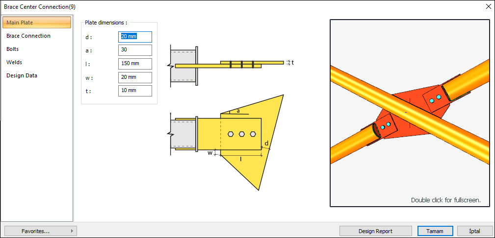
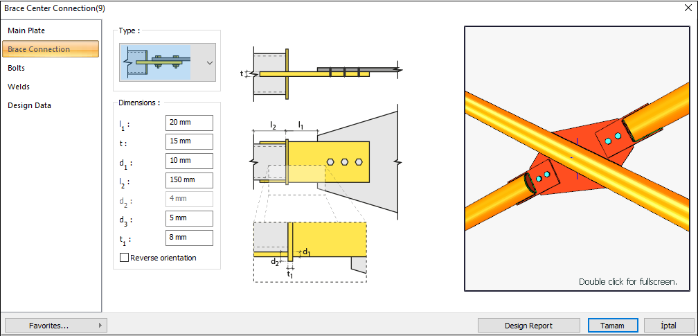
Brace-to-Gusset Plate Connection
GEOMETRY CHECKS
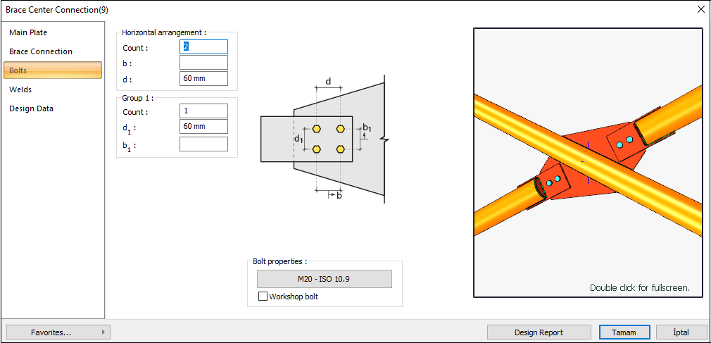
Bolt Spacing
The distance between the centers of bolts is checked per AISC 360-16.
|
smin ≥ 3d |
AISC 360-16 J3.3 |
|
|
|
s |
60 mm |
|
|
|
d |
20 mm |
s =60 mm > smin = 3*20=60 mm |
√ |
Horizontal Edge Distance
The distance from the center of the hole to the edge of the connected part in the horizontal direction is checked per AISC 360-16.
|
Leh ≥ L e-min |
AISC 360-16 J3.4 |
|
|
|
Leh |
69.85 mm |
|
√ |
|
Le-min |
26 mm |
Minimum distance check according to Table J3.4 |
√ |
Vertical Edge Distance
The distance from the center of the hole to the edge of the connected part in the vertical direction is checked per AISC 360-16.
|
Lev ≥ Le-min |
AISC 360-16 J3.4 |
|
|
|
Lev |
45 mm |
Conformity check for Leh ≥ 2d = 2 * 20 = 40 mm application |
√ |
|
Le- min |
26 mm |
Minimum distance check according to Table J3.4 |
√ |
Weld Size
The minimum size of fillet welds is checked according to AISC 360-16 Table J2.4
|
w ≥ wmin |
AISC 360-16 J2.4 |
|
|
|
w |
5.658 mm |
|
√ |
|
wmin |
5 mm |
Table J2.4 |
√ |
STRENGTH CHECKS
Bolt Shear at Brace
The bolt shear limit state of the connection is checked according to AISC 360-16.
|
Ab |
|
|
|
Fn |
|
|
|
Rn |
|
AISC 360-16 J3-1 |
|
ΦRn |
|
|
|
Required |
Ready |
Rate |
Control |
|---|---|---|---|
|
205.872 kN |
212.058 kN |
0.971 |
√ |
Bolt Bearing on Plate
The bearing strength limit states of the connection plate, which are “shear tear out” and “ovalization of bolt hole” for both end and inner bolts, are checked according to AISC 360-16.
|
dh |
20+2=22 mm |
|
|
Lc,edge |
|
|
|
Rn |
|
AISC 360-16 J3-6a |
|
Rn-edge |
|
|
|
Lc,spacing |
|
|
|
Rn-spacing |
|
|
|
Rn |
|
|
|
ΦRn |
|
|
|
Required |
Ready |
Rate |
Control |
|---|---|---|---|
|
205.872 kN |
456.84 kN |
0.451 |
√ |
Bolt Bearing on Gusset
The bearing strength limit states of the connection plate, which are “shear tear out” and “ovalization of bolt hole” for both end and inner bolts, are checked according to AISC 360-16.
|
dh |
20+2=22 mm |
|
|
Lc,edge |
|
|
|
Rn |
|
AISC 360-16 J3-6a |
|
Rn-edge |
|
|
|
Lc,spacing |
|
|
|
Rn-spacing |
|
|
|
Rn |
|
|
|
ΦRn |
|
|
|
Required |
Ready |
Rate |
Control |
|---|---|---|---|
|
205.872 kN |
304.56 kN |
0.676 |
√ |
Weld Strength
The nominal and design strength of the weld is checked according to AISC 360-16
|
Fe |
490000 kN/m2 |
|
|
w |
5.658 mm |
|
|
Fu-plate |
469.999 N/mm2 |
|
|
Fu-brace |
410 N/mm2 |
|
|
tplate |
15 mm |
AISC 360-16 J3-6a |
|
tbrace |
15 mm |
|
|
lw |
150 mm |
|
|
Rnw |
|
|
|
Rn-plate |
|
|
|
RnBM |
|
|
|
Rn |
|
|
|
ΦRn |
|
|
|
Required |
Ready |
Rate |
Control |
|---|---|---|---|
|
205.872 kN |
529.2 kN |
0.389 |
√ |
Whitmore Section Compression Yield
The buckling limit state in withmore section of the plate subjected to compression is checked according to AISC 360-16.
|
K |
0.65 |
|
|
L |
0 mm |
|
|
r |
2.887 mm |
|
|
KL / r |
0 |
|
|
Fy |
355 N/mm2 |
|
|
Ag |
1292.82 mm2 |
|
|
Rn |
|
AISC 360-16 J4-6 |
|
ΦRn |
|
|
|
Required |
Ready |
Rate |
Control |
|---|---|---|---|
|
205.872 kN |
413.056 kN |
0.498 |
√ |
Next Topic