
|
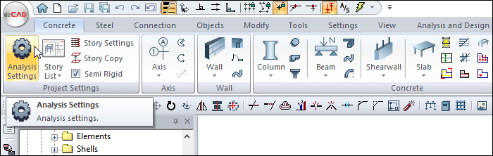
You can use Analysis+Design with appropriate design parameters by opening the Analysis and Design project file, which has the structural system and load model properly arranged. |
-
Click on the Analysis Settings command.
-
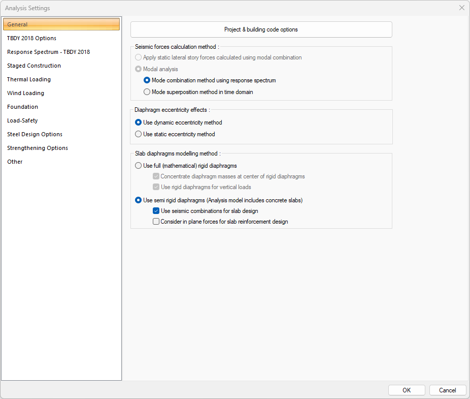
The Analysis Settings dialog will open.
-
In the General tab, select the Seismic Forces Calculation Method as the Mode Combination Method Using Response Spectrum.
-
Select Use Semi Rigid Diaphragms from the Slab Diaphragms Modelling Method section.
-
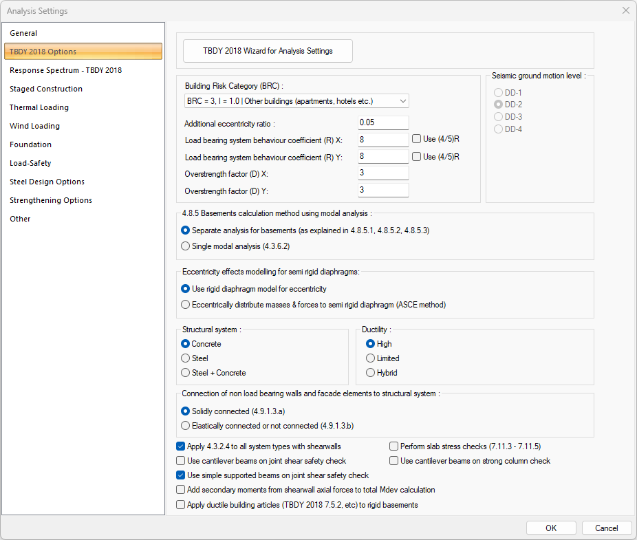
In the TBDY 2018 Options tab, from Basement Calculation Method Using Modal Analysis section, select Separate Analysis for basements.
-
Click the OK button to close the dialog.
-
Click the Analysis and Design tab in the ribbon menu.
-
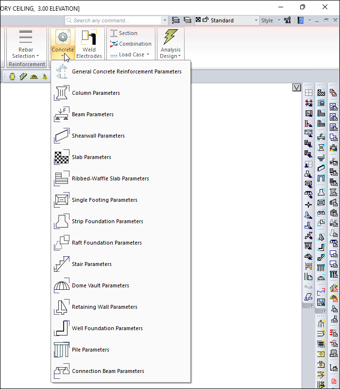
Open the Concrete list from the Design Parameters heading.
-
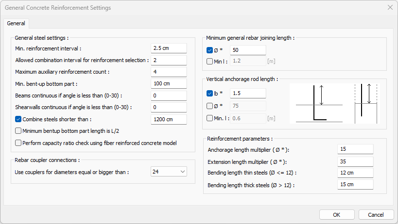
Click the General Concrete Reinforcement Parameters command from the Concrete list .
-
General Concrete Reinforcement Settings dialog will open.
-
Check the concrete parameters.
-
Click the OK button to close the dialog.
-
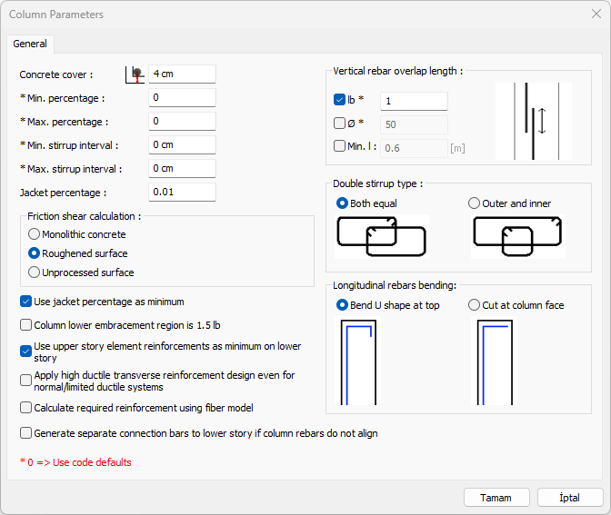
Click the Column Parameters command from the Concrete list .
-
The Column Parameters dialog will open.
-
Check the column parameters.
-
Click the OK button to close the dialog.
-
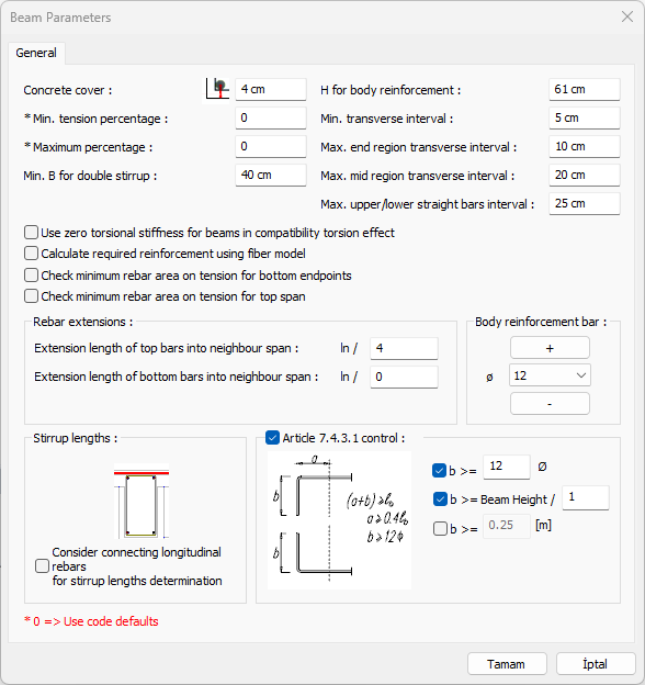
Click the Beam Parameters command from the Concrete list.
-
The Beam Parameters dialog will open.
-
Check the beam parameters.
-
Click the OK button to close the dialog.
-
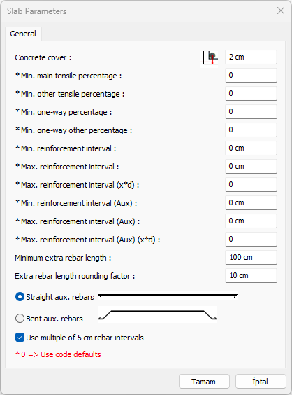
Click the Slab Parameters command from the Concrete list.
-
The Slab Parameters dialog will open.
-
Check the slab parameters.
-
Click the OK button to close the dialog.
-
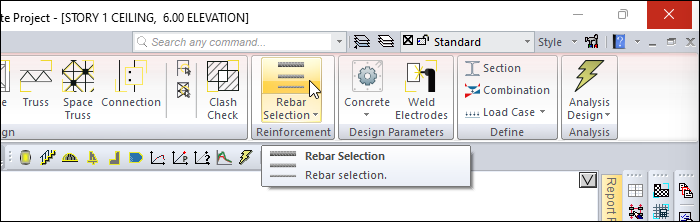
Click the Rebar Selection command from the ribbon menu.
-
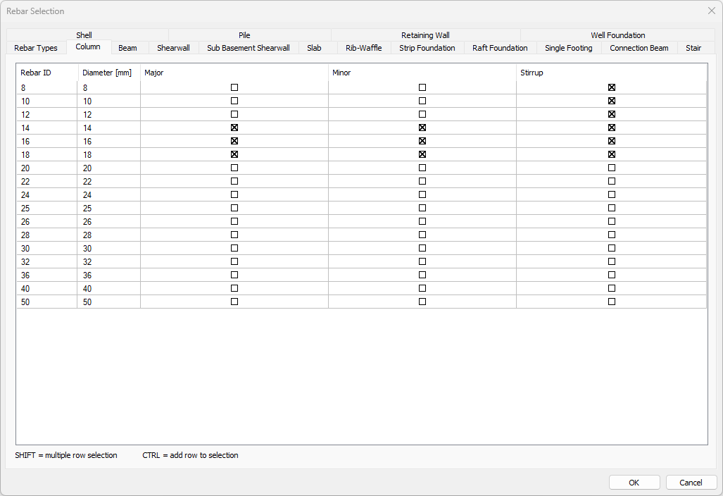
The Rebar Selection dialog will open.
-
Click the Column tab.
-
Check the column longitudinal and transverse reinforcement diameters.
-
Click the Beam tab.
-
Check the beam longitudinal and transverse reinforcement diameters.
-
Click the OK button to close the dialog.
-
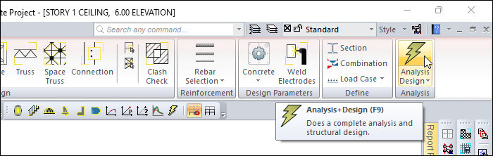
Click the Analysis+Design (F9) command.
-
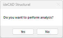
Do you want to perform analysis? question will be asked.
-
Click the Yes button.
-
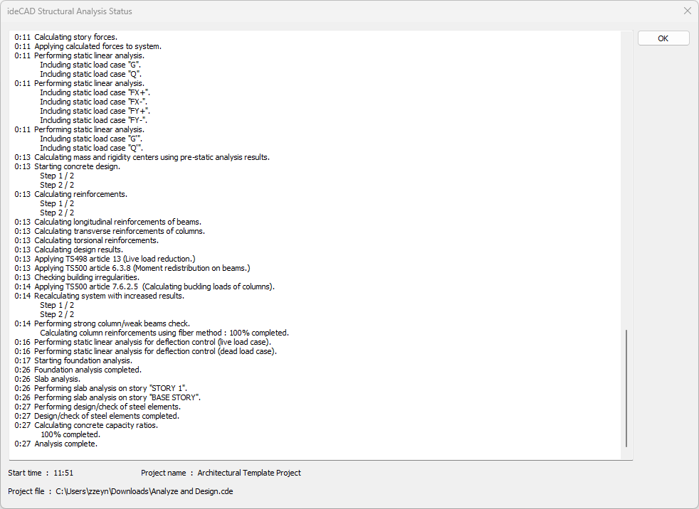
Wait for the analysis to complete in the Analysis Status window.
-
After the analysis is complete, click the OK button to close the window.
-
Combinations for Concrete Design and Steel Design are defined automatically.
-
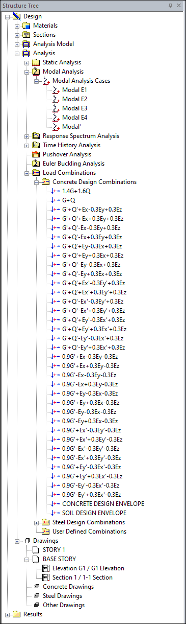
Open the Load Combinations list under the Structure Tree, Analysis heading .
-
Open the Concrete Design Combinations list.
-
The load combinations used for the design of concrete elements will be seen.
-
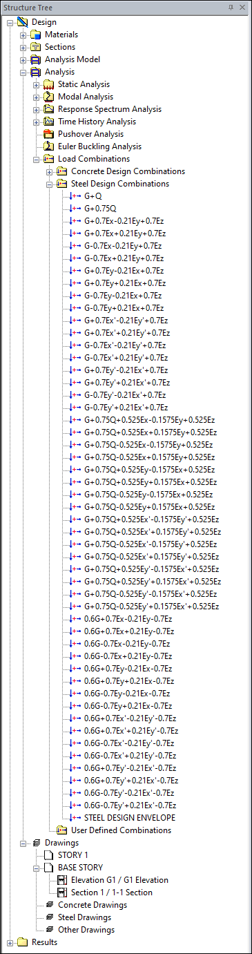
Open the Steel Design Combinations list.
-
The load combinations used for the design of the steel elements will be listed.
Follow the steps of the video below.
Next Tutorial