
With the Shearwall Settings command, the settings of the concrete shearwall such as drawing, offset, material selection, structural material can be accessed.
Location of Shearwall Settings Dialog
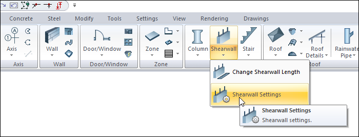
Shearwall toolbar that appears on the screen after the shearwall command is run, by clicking the Setting icon.
A dialog is also opened when double clicked on a shearwall.
In Architectural Program
You can access it under the ribbon menu Home tab, Concrete title.
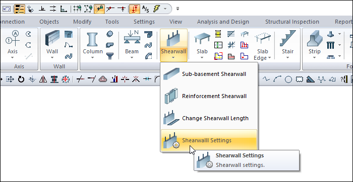
In Structural Program
You can reach it under the ribbon menu Concrete tab, Concrete title
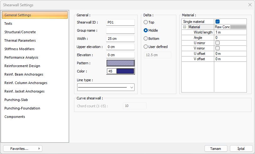
General Settings Tab
|
Specifications |
|---|
|
Shearwall ID The shearwall name is created by placing the P index in front of the number entered here (such as P1, P15). The ideCAD increases these names in the order in which the shearwalls are drawn. shearwall names can also be changed after the shearwall are drawn. The shearwall names that are changed do not have to be P. Any name can be used. |
|
Group name L, U, C etc. To design shearwalls made up of arms as a single shearwall element, they are called groups. shearwalls called the same group; in reinforced concrete design, it is listed under the shearwall group and and the account outputs are prepared as a shearwall group report. |
|
Width Shearwall width refers to the thickness of the shearwall in plan. 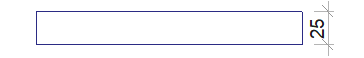
|
|
Upper elevation/Elevation Upper elevation and Elevation parameters are used to shorten or lengthen the shearwall from the top and bottom. As long as zero is left, it is taken as the floor height given in the Column Floor General Settings dialog. In this case, the shearwall lower node is located at the floor base and the upper joint is at the floor ceiling. If a positive value is entered in the upper elevation, the shearwall upper node is extended up to the entered value, if a negative value is entered, the shearwall is shortened downwards. If a positive value is entered in the elevation section, the value entered at the lower end of the column becomes shorter from the bottom. In case of negative value, the shearwall will extend from the bottom. 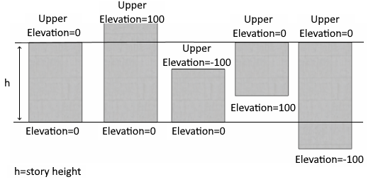
|
|
Color It is the color of shearwall edge lines. The color palette is scrolled by clicking and holding down the left mouse button. The button is released when the desired color is reached. The color box turns into the selected color. If clicked together with the Shift key, the pen thickness of the relevant color can be adjusted. Pen thickness is not noticeable on the screen. The drawing is valid when drawn on paper. |
|
Pattern It is the pattern type valid in the plan for the shearwall. Clicking on Pattern opens the Pattern Settings dialog. In this dialog, the wanted hatch type and color is selected from the hatch types table. |
|
Delta 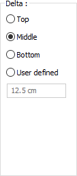
It determines from where the shearwall will be defined according to the axis connecting the nodes at both ends of the shearwall. According to the direction of view, if it coincides with the top edge of the shearwall, the top option is marked, if it coincides with the bottom edge, the bottom option is selected, if it passes through the middle of the shearwall, the middle option is marked. If the virtual shearwall axis will pass through another line, the User Defined option is checked and the distance to the top edge of the shearwall is entered in the bottom data entry box. 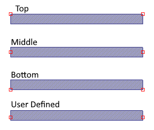
|
|
Material 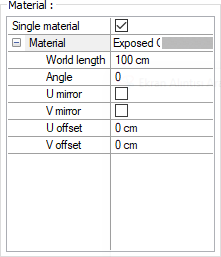
The material to be used on the front, backt and other surfaces of the shearwall is selected from the list. Surfaces are covered with the selected material and displayed as such in renderings. Texture length is entered into the world length. For example; If 1 is entered, the selected material texture is taken as 1 meter and covered on the relevant walls. In the angle, the angle of the texture is entered. Touch the U and V offset. The motion value in the x and y plane is entered. With U and V mirroring, the texture is symmetrical with respect to the y and x planes. By selecting the single material option, the material selected in "Front material" is used on all surfaces of the shearwall. |
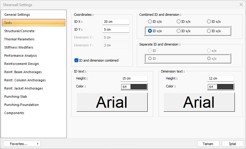
Texts Tab
|
Specifications |
|---|
|
ID X/ID Y X and Y coordinates of the shearwall Name text are entered according to the upper left (if the text is on the shearwall) or the lower corner (if the text is inside the shearwall). If the X value is positive, the text moves from the edge to the right, and if negative, it moves to the left. If the Y value is positive, the text will scroll up, and if it is negative, the text will scroll down. The directions specified here should be considered according to the viewing direction. If the name and size are printed together, the letters are placed according to these coordinates. |
|
Dimension X/Dimension Y X and Y coordinates of the shearwall Size text are entered according to the upper right (if the text is on the shearwall) or the lower corner (if the text is inside the shearwall). If the size X value is positive, the text moves from the edge to the left, if negative, the text moves to the right. If the Y value is positive, the text will scroll up, and if it is negative, the text will scroll down. The directions specified here should be considered according to the viewing direction. Not used if name and size are printed together. |
|
ID and dimension combined The parameters in the Name Text section govern the shearwall name text, and the parameters in the Dimension Text Settings section manage the shearwall size text. |
|
Height The height of the name and size text is entered. |
|
Color The color of the texts is adjusted. The color is selected by clicking on the color box with the left mouse button. When the font box below is clicked, the font of the name and size text can be changed. |
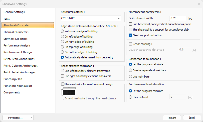
Structural/Concrete
|
Specifications |
|---|
|
Structural material The structural material to be used in the shearwall element is selected from the list. Structural material can be defined as a reinforced concrete element under Materials in Building Tree. |
|
Edge status determination for article 4.3.2.4b 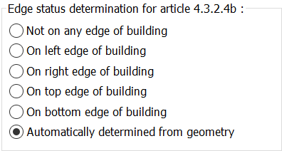
It is the option used to determine the condition of the side walls while checking the overturning moment of the side walls specified in TBDY 4.3.2.4(b). This condition can be controlled automatically as well as at the discretion of the user. |
|
Shear strength calculation 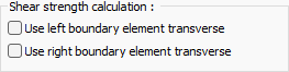
For shear strength calculation, the use of left and right boundary element transverse is decided. |
|
Use mesh reinforcement 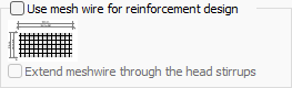
The use of mesh wire for reinforcement design is activated. If desired, the meshwire can be extended through the head stirrups. |
|
Calculate as shell/Finite element width Check this option to model the shearwall using the finite element method. It will be calculated by dividing the shearwall meshes by using the finite element width below. If the option is not selected, the shearwall will be modeled as a single piece of sheet. |
|
Sub-basement panel/vertical discontinuous panel Properties of an entered shearwall become active when opened. If the shearwall is a sub-basement shearwall or a shearwall that does not continue throughout the whole floor, this option is checked. When marked, the relevant shearwall is not included in the cutting area effective in alpha calculation and B1 irregularity control. In addition, the internal force amplification coefficient specified in TBDY 2018 article 4.3.4.9 is not applied. |
|
This shearwall is a support for a cantilever slab This option can be selected if the shearwall console is the support of a floor. Otherwise, it should not be marked. |
|
Fixed support on bottom If it is selected, the lower end of the shearwalls that are not vertical in the vertical are flush-mounted. This option should be selected for shearwalls that continue on lower floors. Removing the mark creates a vertical continuity problem in the model. This option can be unchecked if the wall has columns at both ends and beams below, if the shearwall is only connected to the columns. |
|
Rebar coupling This option is activated if it is wanted to make anchoring reinforcement attachment instead of the overlapped joint on the shearwall. The confounding value is entered in the staggering distance box for the coupling application. |
|
Connection to foundation 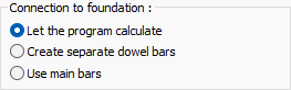
Foundation connections are found automatically. If desired, one of the options "Create separate dowel bars or use main bars" is selected. |
|
Sub basement level elevation 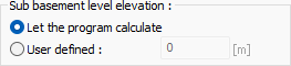
The sub-basement level elevation for foundation is found automatically. In some special cases, the desired sub basement level elevation can be entered manually in the box by using the user defined option. |
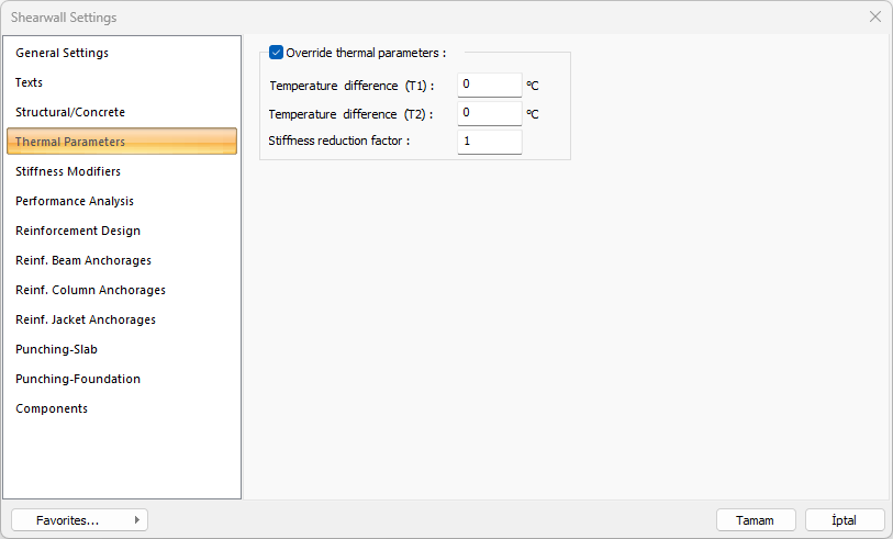
Thermal Parameters Tab
|
Specifications |
|---|
|
Temperature Parameters When checked, it activates T1 and T2 temperature loads on element basis. |
|
Temperature difference (T1) The temperature difference of T1 loading is given. |
|
Temperature difference (T2) The temperature difference of the T2 loading is given. |
|
Stiffness reduction factor The stiffness reduction factor to be used in the temperature calculation for the relevant element is given. |
Stiffness Modifiers Tab
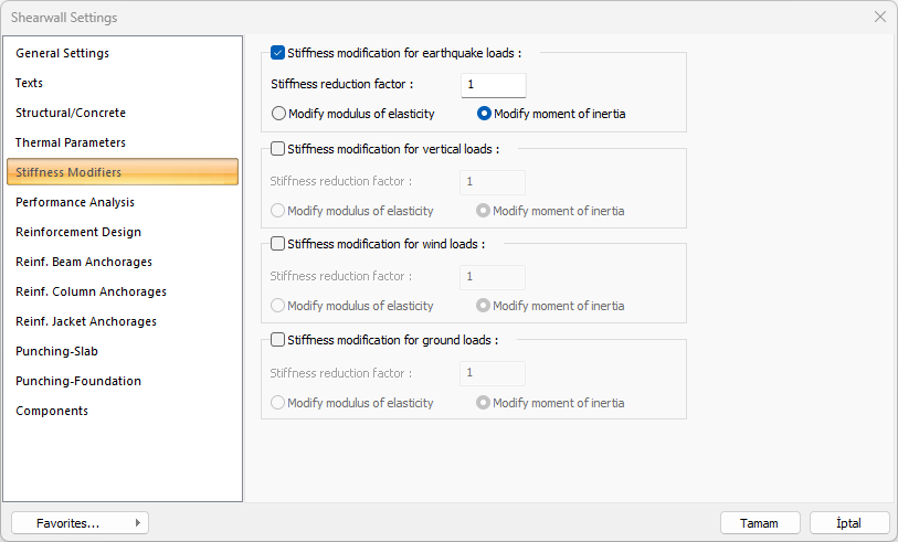
This tab is only visible when the Shearwall is selected and Object Properties and Shearwall Settings are opened. In this tab, shearwall stiffness can be reduced by a certain anchoragevalue separately for earthquake, vertical, wind and soil thrust loads. Stiffness reduction can be applied optionally on the basis of element elasticity modulus or moment of inertia.
|
Specifications |
|---|
|
Stiffness modificatiın for earthquake loads 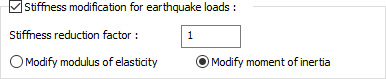
Shearwall stiffness can be reduced by a specific anchoragevalue separately for earthquake, vertical, wind and soil thrust loads. Stiffness reduction can be applied optionally on the basis of element elasticity modulus or moment of inertia. E = Reduction Factor * E or I = Reduction Factor * Applied as I. |
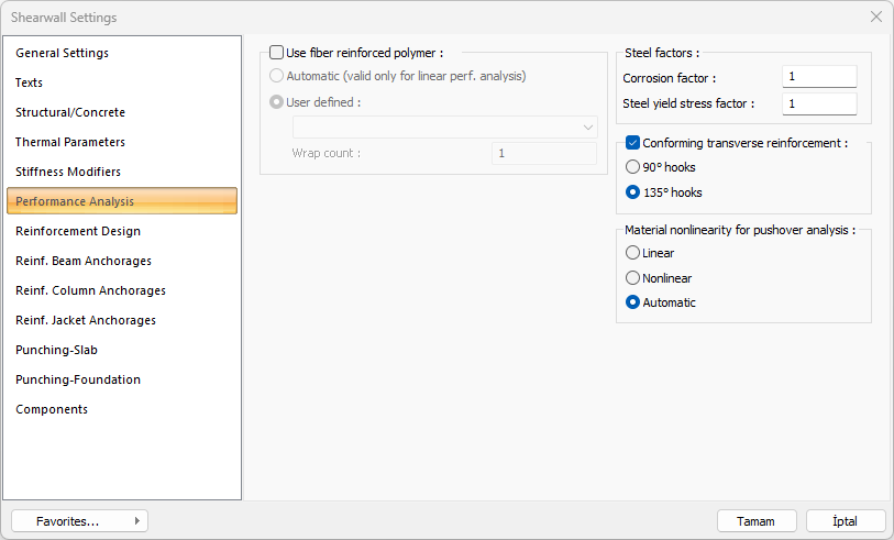
Performance Analysis Tab
|
Specifications |
|---|
|
Use fiber reinforced polymer 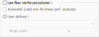
In shearwalls that will be reinforced with fiber polymer, Fiber polymer properties are set by checking this option. Reinforcement is made by selecting one of the fiber polymers defined in the Fiber Reinforced Polymer Library and the count of wrap. |
|
Corrosion factor It is a ratio used in building performance analysis. With the ratio written on this line, the wear occurring in the existing structures and reinforcements exposed to the corrosion conditions specified in the earthquake regulation can be taken into account in the performance calculation of the structure. The value defined in this row is multiplied with the existing reinforcement areas and the value found at the result of multiplication is considered as the reinforcement area. The mevcutal the yenial = multiplier * |
|
Steel yield stress factor It is used to reduce the steel yield stress of the elements. The value entered in this row is multiplied by the steel yield value of the element. new steel yield value * current steel yield value of the multiplier = |
|
Conforming transverse reinforcement If there is transverse reinforcement at the upper and lower ends of the column belonging to the existing structure, this option is checked. Choose one of the 90 ° or 135 ° hooks options. |
|
Material nonlinearity for pushover analysis 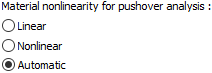
By selecting one of the linear, nonlinear (distributed plastic behavior) and automatic options, the material model defined in the shearwall is determined while performing nonlinear pushover analysis. |
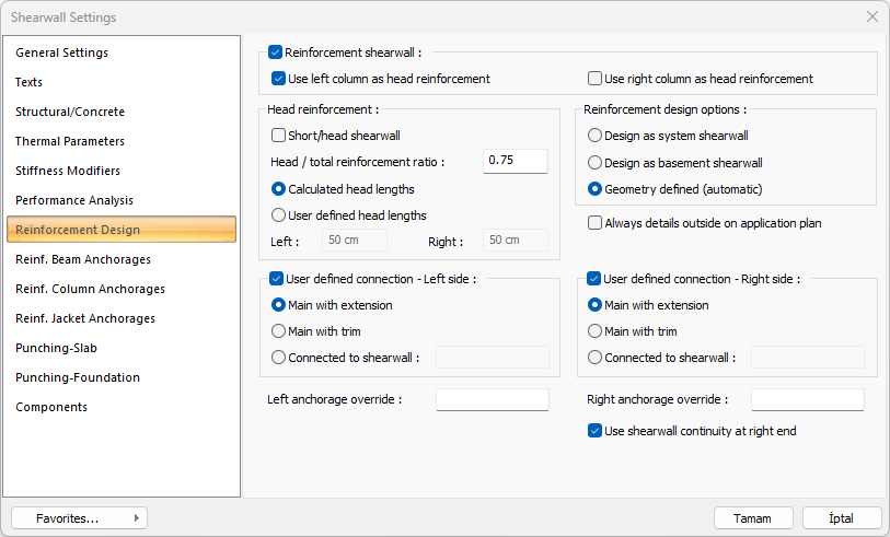
Reinforcement Design Tab
|
Specifications |
|---|
|
Reinforcement shearwall If the shearwall is reinforcement shearwall entered, this line should be marked. Use right and right columns as headings: If the columns on the right and left of the reinforcement shearwall are required to be accepted as headings for the reinforcement walls, the options are marked. |
|
Short/head shearwall This option is selected for short shearwalls that do not provide the 1/6 size ratio in group shearwalls and are desired to be shown in the calculations and drawings as the heading of the other shearwall. If this option is marked, the stirrup and longitudinal reinforcement design and drawing will be made by including the shearwall headers in the relevant shearwall. 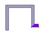
The short shearwall, which is shown as selected in the sample screenshot, is included in the shearwall group and marked as a short title shearwall in its properties. |
|
Head/total reinforcement ratio The default value is 0.50. This parameter; The wall end zone creates a lower limit for the amount of wall end reinforcement according to the total amount of reinforcement in the walls to be arranged. In other words, the amount of end reinforcement is determined at least as much as the ratio given to this row, besides the regulation conditions. For example, given the value 0.5, if the amount of reinforcement required for the whole wall is 100 cm2, 50 cm2 is placed in the middle area and 25 cm2 reinforcement is placed in the end regions for the left and right. Placed reinforcements are not selected less than the required reinforcement as per the regulation. |
|
Head lengths 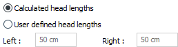
Unless otherwise stated, the ideCAD determines the shearwall end zone lengths according to the conditions specified in TBDY. However, if wanted, the length of the header region can be adjusted to certain values. If the calculated head lengths, the head length for the respective shearwall is adjusted according to the TDY conditions. If user defined head lengths is checked, the length of the head is arranged as much as the length values given in the left and / or right lines for the relevant shearwall. |
|
Reinforcement design options 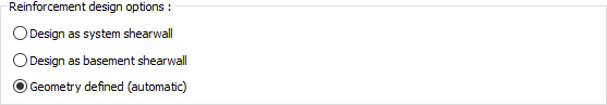
The reinforcement connections of the intersecting shearwalls are created according to the static state of the shearwalls . In the system walls, the horizontal body fittings are connected to each other by extending them into each other, while the basement perimeter walls are anchored to these system shearwalls. You can change how this wall is reinforced with body reinforcement from the reinforcement design options. Automatically, shearwalls that continue on the upper floors are classified as system shearwalls. Shearwalls below the rigid floor height and not continuing on the upper floors are classified as basement perimeter shearwalls. In cases that do not comply with these classifications, the user can determine how the web reinforcement of the selected shearwall will be reinforced with these options. Design as system shearwall: When the option is selected, the reinforcement design is made as the carrier system shearwall of the selected shearwall/shearwalls. Design as basement shearwall : When the option is selected, the selected shearwall/ shearwalls are designed as basement perimeter shearwall. Geometry defined (automatic): When the option is selected, the ideCAD automatically decides the reinforcement design of the walls/shearwalls. |
|
Always details outside on application plan When marked, it enables the opening of the details regardless of the position and proximity / distance of the other elements around the shearwall. |
|
User defined connection 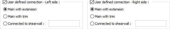
The ideCAD automatically creates the most suitable drawing according to the connection status of the shearwalls, the angle between the shearwalls and the shearwall type (basement or system shearwall). These drawings can be intervened by the user if desired. In the case where two or more shearwalls are joined, two shearwalls can be user-defined as priority. |
|
Main with extension By selecting the "Main with extension" option for main shearwalls, the connection type of shearwall rebar for the left and right ends of the shearwall is determined. An example of a connection of two basement shearwalls: 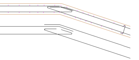
An example of system shearwall and basement shearwall connection: 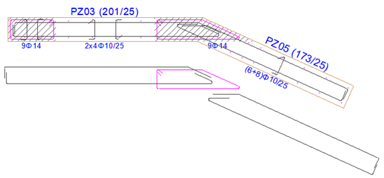
|
|
Main with trim By selecting the “Main with trim” option for main shearwalls, the connection type of shearwall rebar for the left and right ends of the shearwall is determined. An example of a connection of two basement shearwalls: 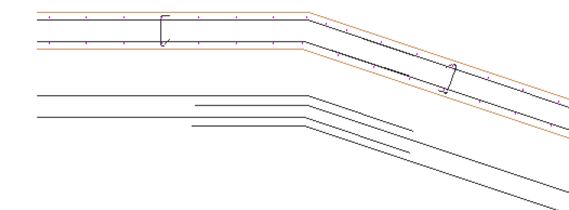
An example of system shearwall and basement shearwall connection: 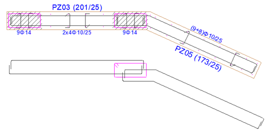
|
|
Connected to shearwall The shearwall name to be anchored is entered as a parameter. Anchoring is made to the defined shearwall. P15 shearwall connected to P03 shearwall: 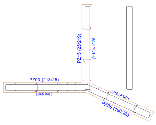
P15 shearwall connected to P03 shearwall: 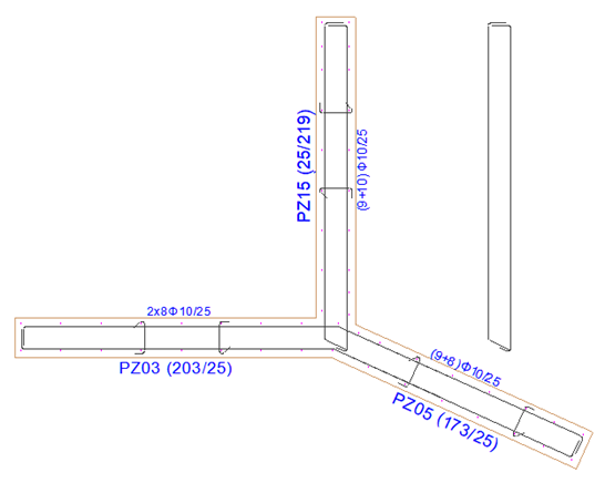
|
|
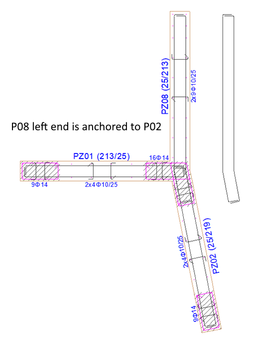
Left anchorage override/Right anchorage override In the case where three or more shearwalls are joined, the anchorage of the shearwalls can be user-defined. The drawing can be taken in the following figures by changing the "Left anchorage override" parameter of P08 shearwall as user-defined. 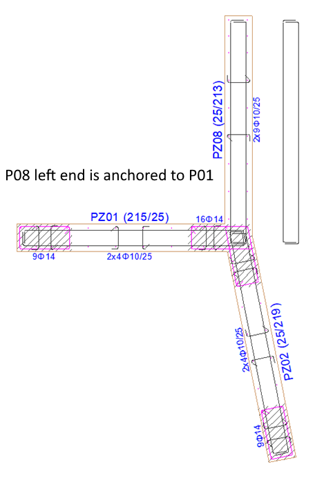
|
|
Use shearwall continuity at right end With this option, the shearwall horizontal rebars can be cut at the desired junction point, regardless of the 12m rebar length condition, and overlapped joints can be made or anchoring to the column can be provided. For shearwall P08, the continuous accept shearwall feature is active at the right end: 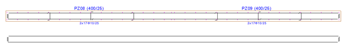
For shearwall P08, the continuous accept shearwall feature at the right end is not active: 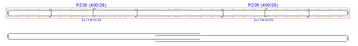
For shearwall P08, the continuous accept shearwall feature is active at the right end: 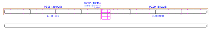
For shearwall P08, the continuous accept shearwall feature at the right end is not active: 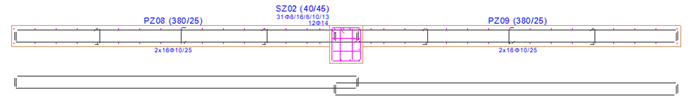
|
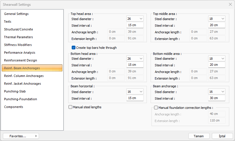
Reinforcement Beam Anchorages Tab
In this tab, the shearwall and connection reinforcement settings of the beams above and below the Reinforcement shearwall are made.
|
Specifications |
|---|
|
Steel diameter Reinforcement range values are entered for the relevant connection. |
|
Steel interval Reinforcement range values are entered for the relevant connection. |
|
Anchorage length It becomes active if the "Manual steel lengths" option is selected and the anchoragelength can be entered as user-defined. |
|
Extension length It becomes active if the "Manual steel lengths" option is selected and the anchorage length can be entered as user-defined. |
|
Create top bars hole through If it is marked, it arranges the top anchorage reinforcements in the reinforcement walls as piercing reinforcement to a top wall. The lower zone anchorage reinforcement settings will be the same as the upper zone anchorage reinforcement settings. It does not need to be intervened. |
|
Manual steel lengths When the option is selected, the inactive anchorage and extension length options become active. The user determines the anchorage and extension length manually. |
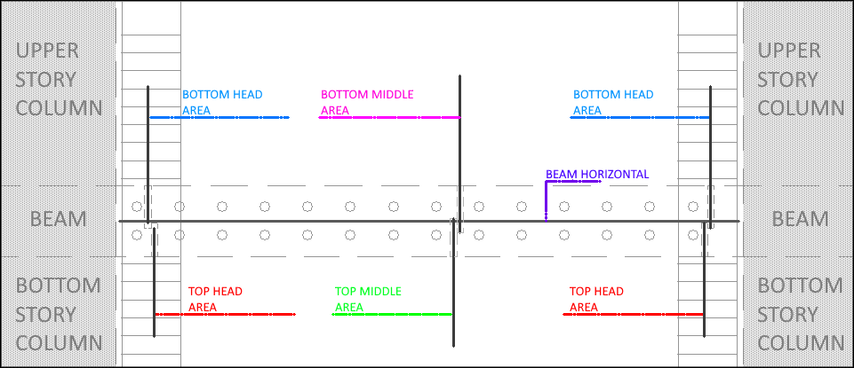
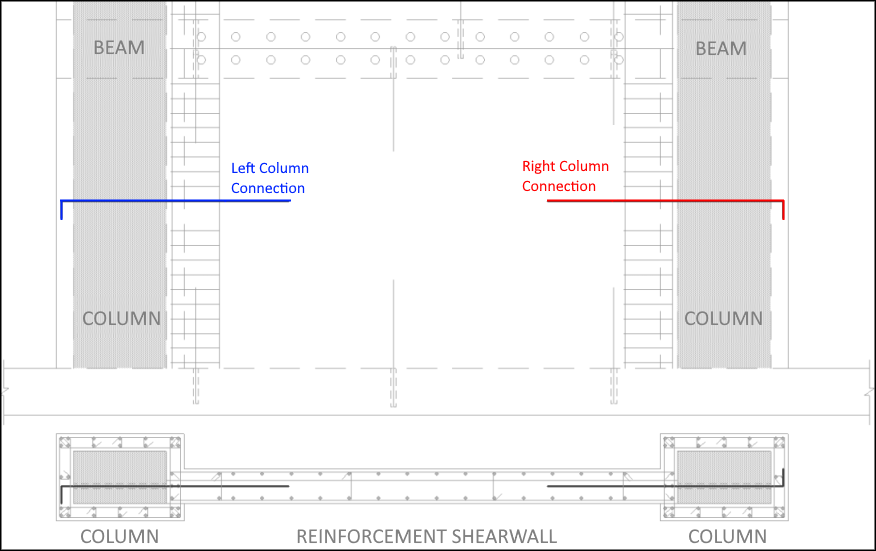
The regions and reinforcement positions of the anchors are shown below according to the colors given:
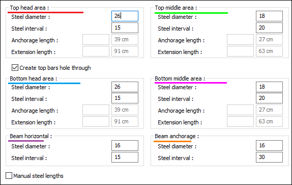
In the case that the anchorage are not created through a hole
In the case that the creating hole through by anchorage
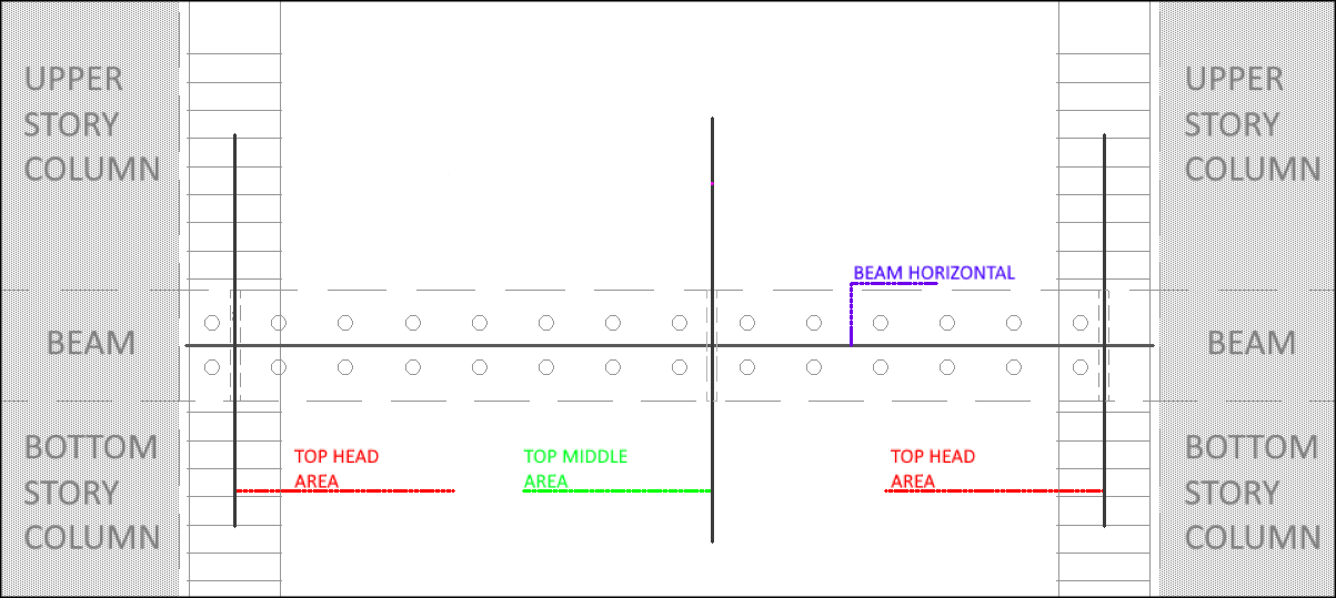
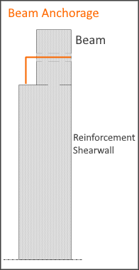
Beam Anchorage
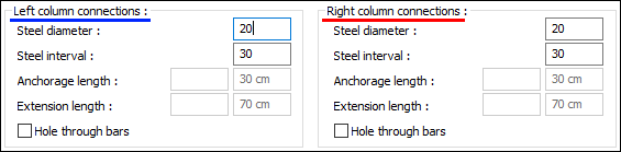
Reinforcement Column Anchorages Tab
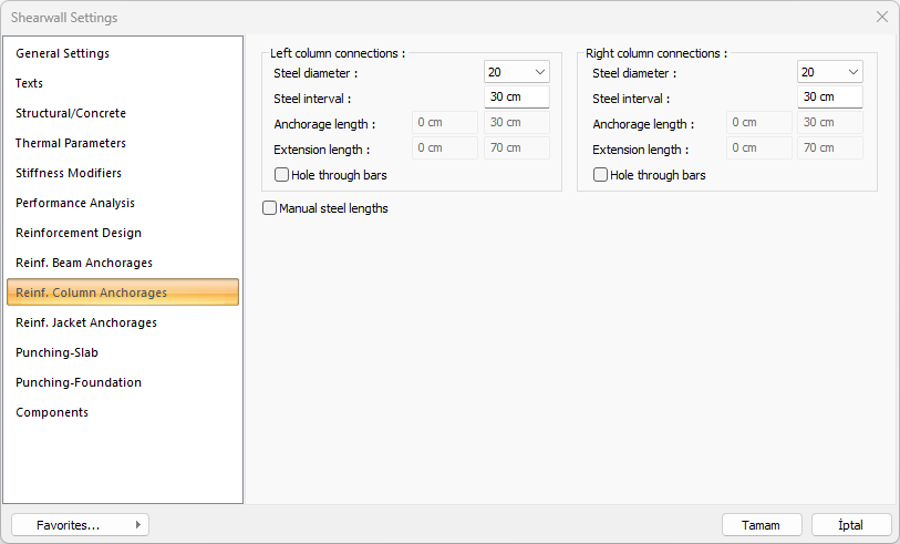
In this tab, the settings of the connection reinforcements between the column elements on the right and left of the Reinforcement Panel are made.
The regions and reinforcement positions of the anchors are shown below according to the colors given:
|
Specifications |
|---|
|
Steel diameter Steel diameter values are entered for the relevant connection. |
|
Steel interval Steel interval values are entered for the relevant connection. |
|
Anchorage length It becomes active if the "Manual steel lengths" option is selected and the anchorage length can be entered as user-defined. |
|
Extension length It becomes active if the "Manual steel lengths" option is selected and the anchorage length can be entered as user-defined. |
|
Hole through bars If marked, it arranges the column anchorage reinforcements in the reinforcement walls as hole anchorage to the next elements. |
|
Manual steel lengths When the option is selected, the inactive anchorage and extension length options become active. The user determines the anchorage and extension length manually. |
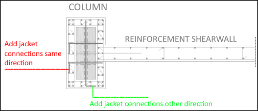
Reinforcement Jacket Anchorages Tab
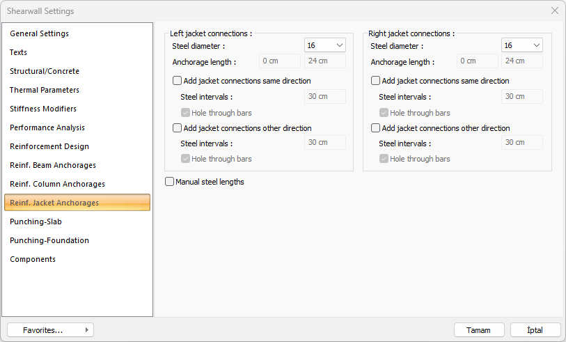
In this tab, the settings of the reinforcement jacket anchorages of the mantle made column elements located on the right and left of the reinforcement shearwall are made.
The regions and reinforcement positions of the anchorages are shown below according to the colors given:
|
Specifications |
|---|
|
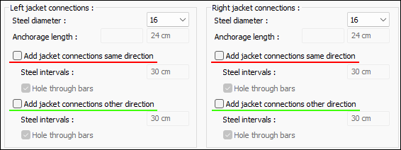
Steel diameter Reinforcement range values are entered for the relevant connection. |
|
Anchorage length It becomes active if the "Manual steel lengths" option is selected and the anchorage length can be entered as user-defined. |
|
Steel intervals Steel distance values are entered for the relevant connection. |
|
Hole through bars If marked, it arranges the column anchorage reinforcements in the reinforcement walls as hole anchorage to the next elements. |
|
Manual steel lengths When the option is selected, the inactive anchorage and extension length options become active. The user determines the anchorage and extension length manually. |
|
Add jacket connections same direction When the option is checked, jacket connections in the same direction are added. |
|
Add jacket connections other direction When the option is checked, jacket connections in the same direction are added. |
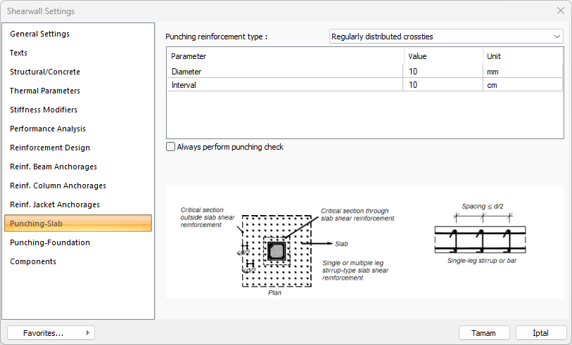
Punching-Slab Tab
|
Specifications |
|---|
|
Punching reinforcement type 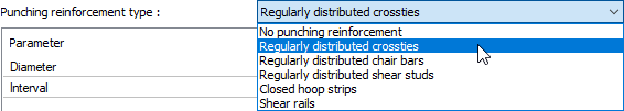
Punching reinforcement types described in Article 7.11.11 and Article 7.11.12 of TBDY 2018 can be selected from the list for the vertical bearing element being treated. If stapling reinforcement will not be used, "No punching reinforcement" type can be selected. You can edit the values given in the dialog according to the type selected. |
|
Always perform punching check If the option is checked, punching check is always performed. |
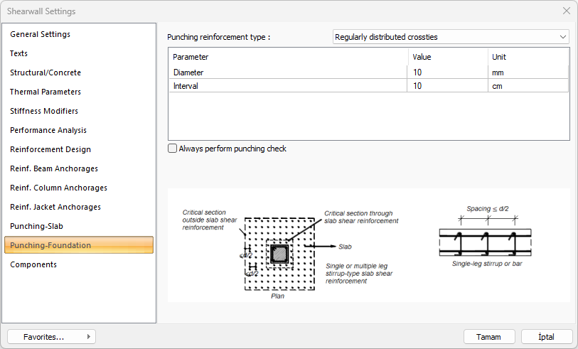
Punching-Foundation Tab
|
Specifications |
|---|
|
Punching reinforcement type
Punching reinforcement types described in Article 7.11.11 and Article 7.11.12 of TBDY 2018 can be selected from the list for the vertical bearing element being treated. If stapling reinforcement will not be used, "No punching reinforcement" type can be selected. You can edit the values given in the dialog according to the type selected. |
|
Always perform punching check If the option is checked, punching check is always performed. |
Components Tab
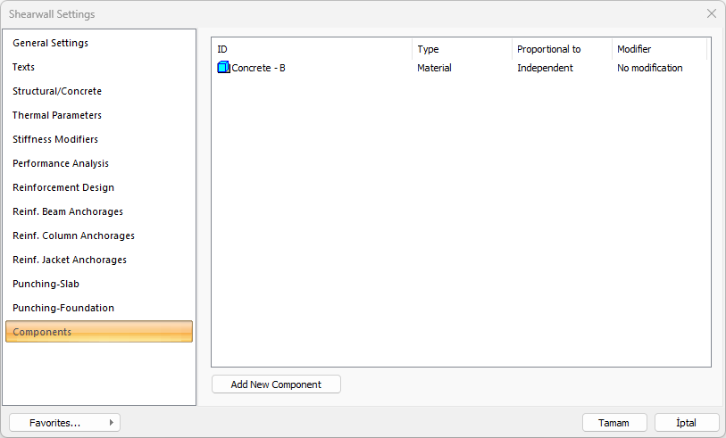
Add Building Components: Assigns the projected building materials to the object for detailed building components metrics.
-
Click on the building components button.
-
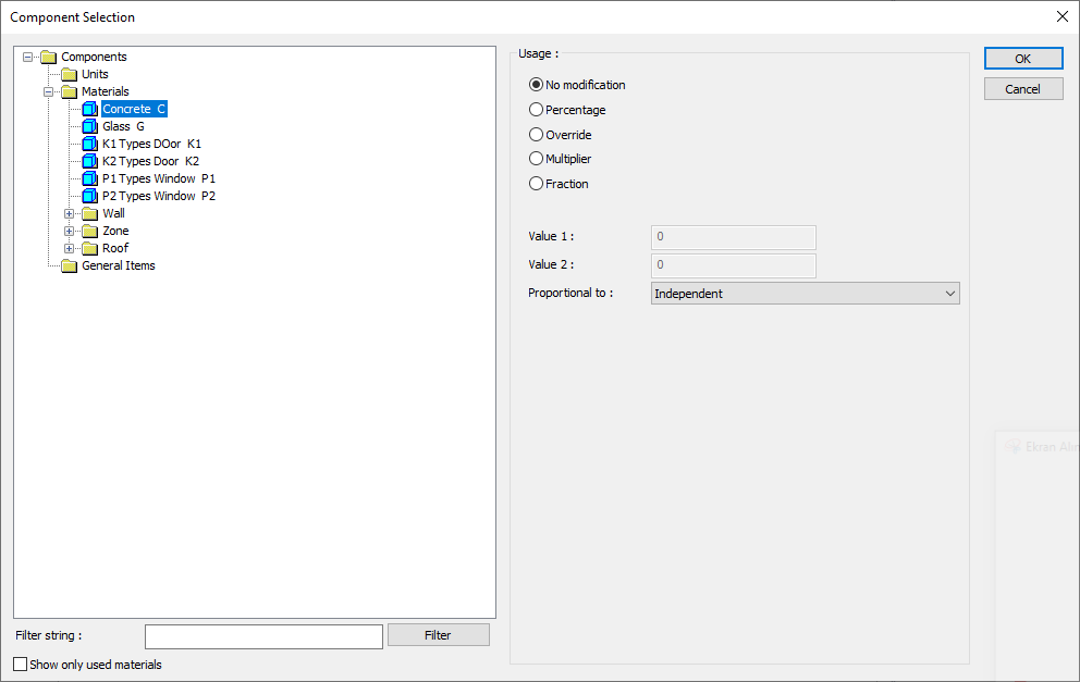
The Component Selection dialog will open.
-
In this dialog, click on the folder related to the material from the list on the left. Click on the material you want to use.
-
Set the parameters on the right.
-
Click the OK button. The "Component Selection" dialog will be closed. A summary line of the material will appear in the Building Components tab. More than one material assignment to an object can be done this way.
The parameters available in the component selection dialog are:
In the usage section
No modification: The amount of material to be assigned for the object in question is marked when it is desired to be used in the size that was previously specified in the material definition.
Percentage: This line is marked when it is desired to be used with the percentage of the amount previously determined in the material definition, as much as the value entered in the "Value 1" line in the same dialog. For example, if the material quantity is 70, if the line “Value 1” says 40, it means the material amount will be used up to 40 * 70%.
Override: This line is marked so that the quantity entered in the “Value 1” line in the same dialog will be used instead of the quantity previously determined in the material definition.
Multiplier: This line is marked in order to use the value found at the end of the multiplication of the value entered in the "Value 1" line in the same dialog with the amount previously determined in the material definition.
Fraction: This line is marked so that the amount determined in the material definition before will be used as the fraction value created by the values entered in the "Value 1" and "Value 2" lines in the same dialog. "Value 1" is the denominator "Value 2" is the denominator.
Proportional to: It is determined to what scale-area, circumference, length etc.-, region-side area, top, edge etc.- the material will be proportioned to. The content of the proportional list box is automatically determined according to the object and the size of the material. For example, a different list will be created if an operation is made for the column, a different list will be created for the library, a different list for the volume, and a different list for the field.
The lines that appear in the Proportion list according to the column object and material size are as follows.
|
Shearwall |
||
|
Measure |
Listed |
Explanation |
|
Constant |
Independent |
The fixed measure used will be used exactly as the amount. |
|
Length |
Independent |
It means that the length measure found while defining the material will be used exactly as the length value. |
|
Front length |
It means that the length of the material will be found by multiplying the length of the material found while defining the material and the length of the front side according to the shearwall viewing direction. |
|
|
Back length |
It means that the length of the material will be found by multiplying the length of the back side according to the viewing direction of the shearwall with the length measure found while defining the material. |
|
|
Average length |
It means that the length of the material will be found by multiplying the length measurement found when defining the material and the average length value found from the length of the front and back sides of the shearwall. |
|
|
Average height |
It means that the length of the material will be found by multiplying the length value found by taking the average of the height of the left and right ends of the shearwall with the length measure found while defining the material. |
|
|
Thickness |
It means that the length of the material will be found by multiplying the length measure found when defining the material and the thickness of the shearwall. |
|
|
Area |
Independent |
It means that the area measure found while defining the material will be used exactly as the amount. |
|
Front area |
The value to be found by multiplying the area measure found while defining the material and the area of the surface on the front according to the viewing direction of the shearwall will be used as the material area. |
|
|
Back area |
It means that the value to be found by multiplying the area measure found while defining the material with the area of the surface on the back side according to the viewing direction of the shearwall will be used as the material area. |
|
|
Front and back area |
The value found by multiplying the area measure found while defining the material and the sum of the front and back areas of the shearwall will be used as the material area. |
|
|
Start area |
The value to be found by multiplying the area measure found while defining the material and the area of the surface on the left according to the viewing direction of the shearwall will be used as the material area. |
|
|
End area |
The value to be found by multiplying the area measure found when defining the material and the area of the surface on the right according to the viewing direction of the shearwall will be used as the material area. |
|
|
Start and end area |
The value found by multiplying the area measure found when defining the material and the sum of the left and right surface areas of the shearwall will be used as the material area. |
|
|
Top area |
The value to be found by multiplying the area measure found when defining the material with the area of the surface remaining on the shearwall means to be used as the material area. |
|
|
Bottom |
The value to be found by multiplying the area size found when defining the material and the area of the surface under the shearwall means to be used as the material area. |
|
|
Top and bottom area |
It means that the value found by multiplying the area measure found when defining the material and the sum of the surface areas on the upper and lower sides of the shearwall will be used as the material area. |
|
|
Side area |
The total value found by multiplying each of the surfaces on the sides of the shearwall with the area measure found when defining the material means to be used as the material area. |
|
|
Volume |
Independent |
It means that the volume measurement found when defining the material will be used exactly as the volume value. |
|
Volume |
It means that the volume measure found when defining the material will be used by multiplying the shearwall volume. |
|
|
Count |
Independent |
The count measure found while definin
|
|
Count |
The count measure found when defining the material, as the count of materials It means it will be used exactly. |
|
Next Topic