
This message is created by giving the element name and solid at the beginning of the report.
For example, SW1 Ground Story, Capacity ratio >1
Three possible solutions to increase the beam capacity ratio less than 1 are explained below.
Group shearwall capacity design ratios are calculated under the influence of axial force and biaxial bending using the fiber model. Group shearwall capacity design ratios are given for shearwall concrete.
Possible Solutions
-
The thickness of the curtains or their length in plan can be increased to the shearwall group.
-
Shearwall cap area reinforcements can be increased.
-
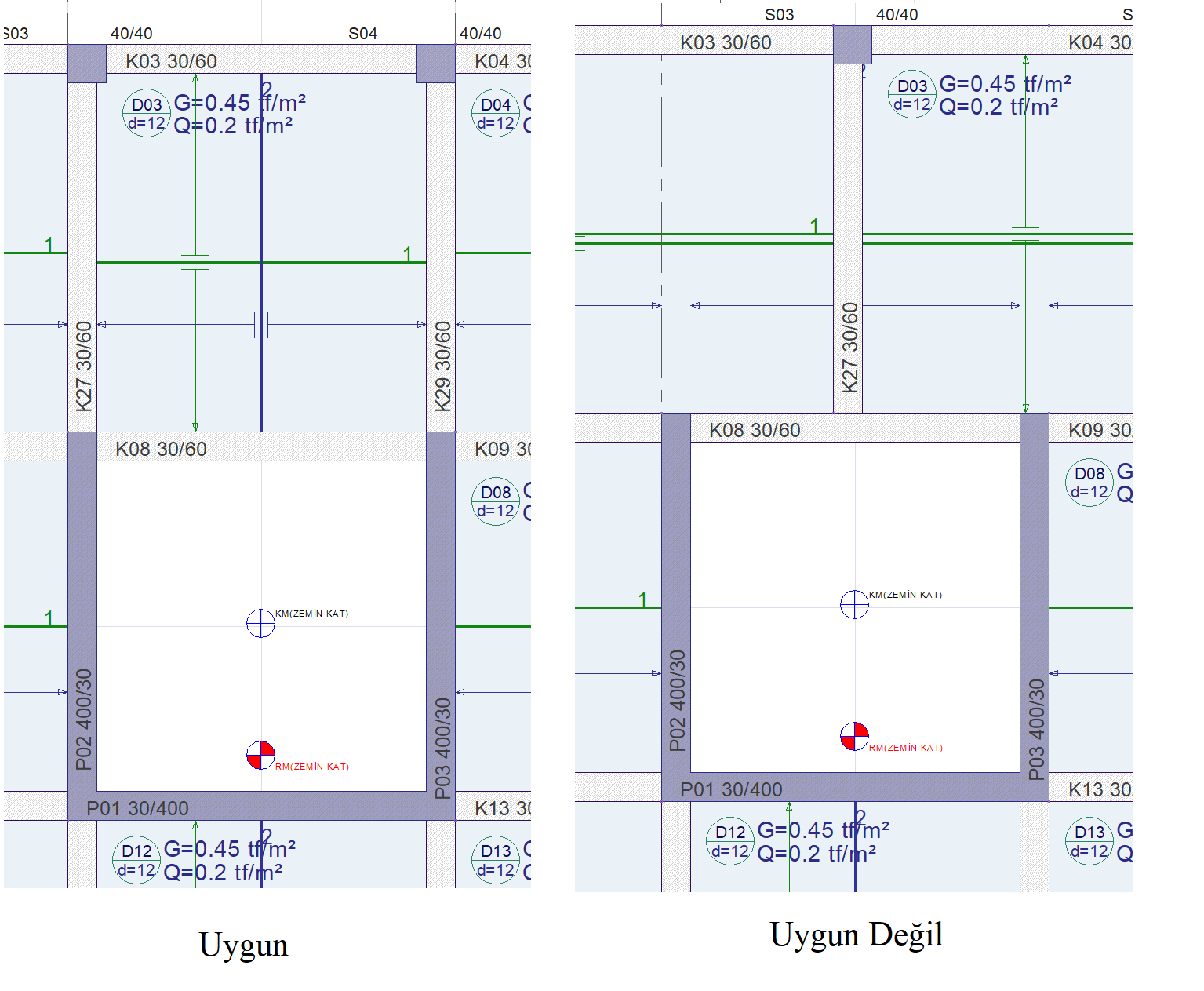
Appropriate carrier system arrangement can be made.
-
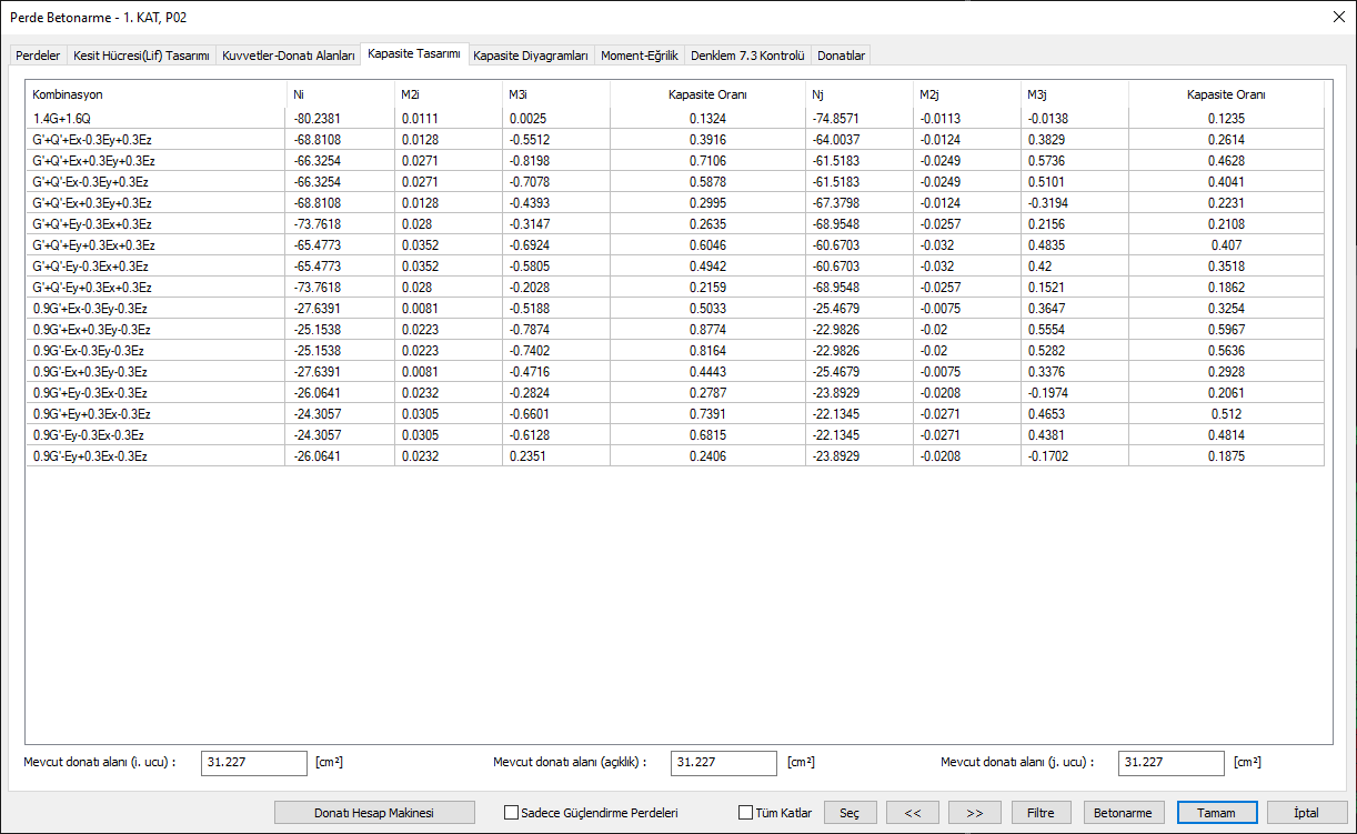
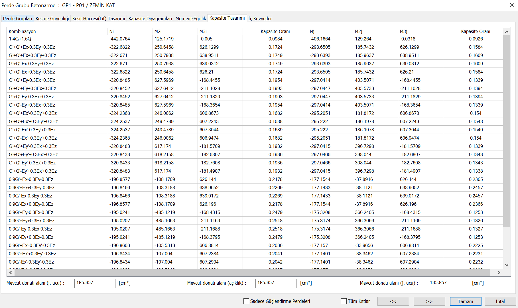
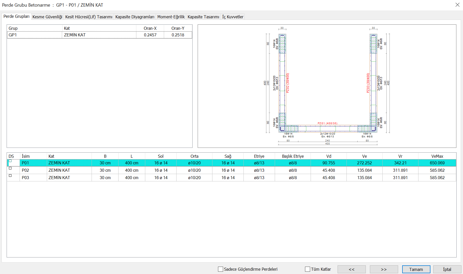
Detailed information of the capacity ratios in Polygon Shearwalls can be seen in the Capacity Design tab of the Shearwall Group Concrete window . By using this section, it can be seen at which end of the polygonal shearwall, under which combination effect, the capacity ratio is exceeded and can be intervened appropriately. At the same time , the Ratio-X and Ratio-Y values specified in the Shearwall Groups tab also show the largest capacity ratios in their dominant direction.
-
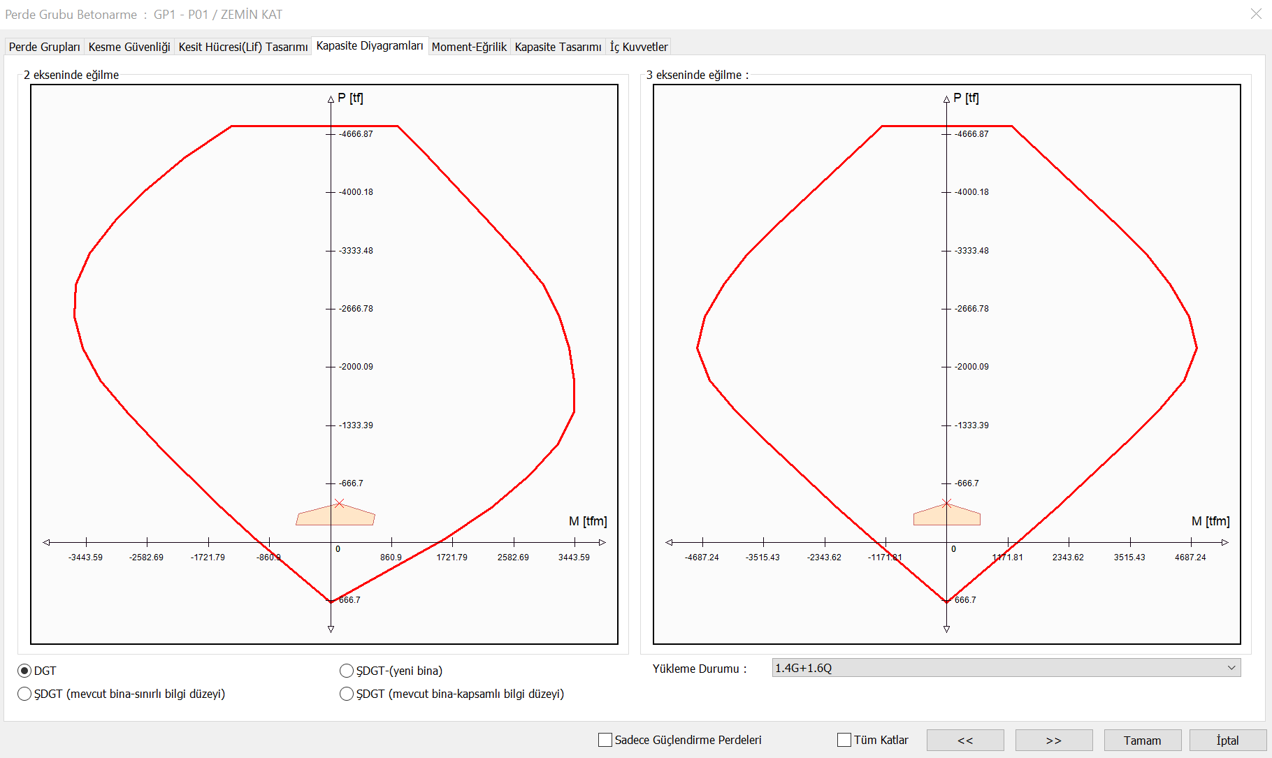
In the Capacity Diagrams tab of the Shearwall Group Reinforced Concrete window , the interaction diagram under the effect of axial force and biaxial bending in the 2 and 3 directions of the polygonal wall can be seen. In addition, the envelope area due to all loading combinations is also visible. By using the Capacity Diagrams tab, it can be determined under which force the shearwall is forced.
Next Topic