
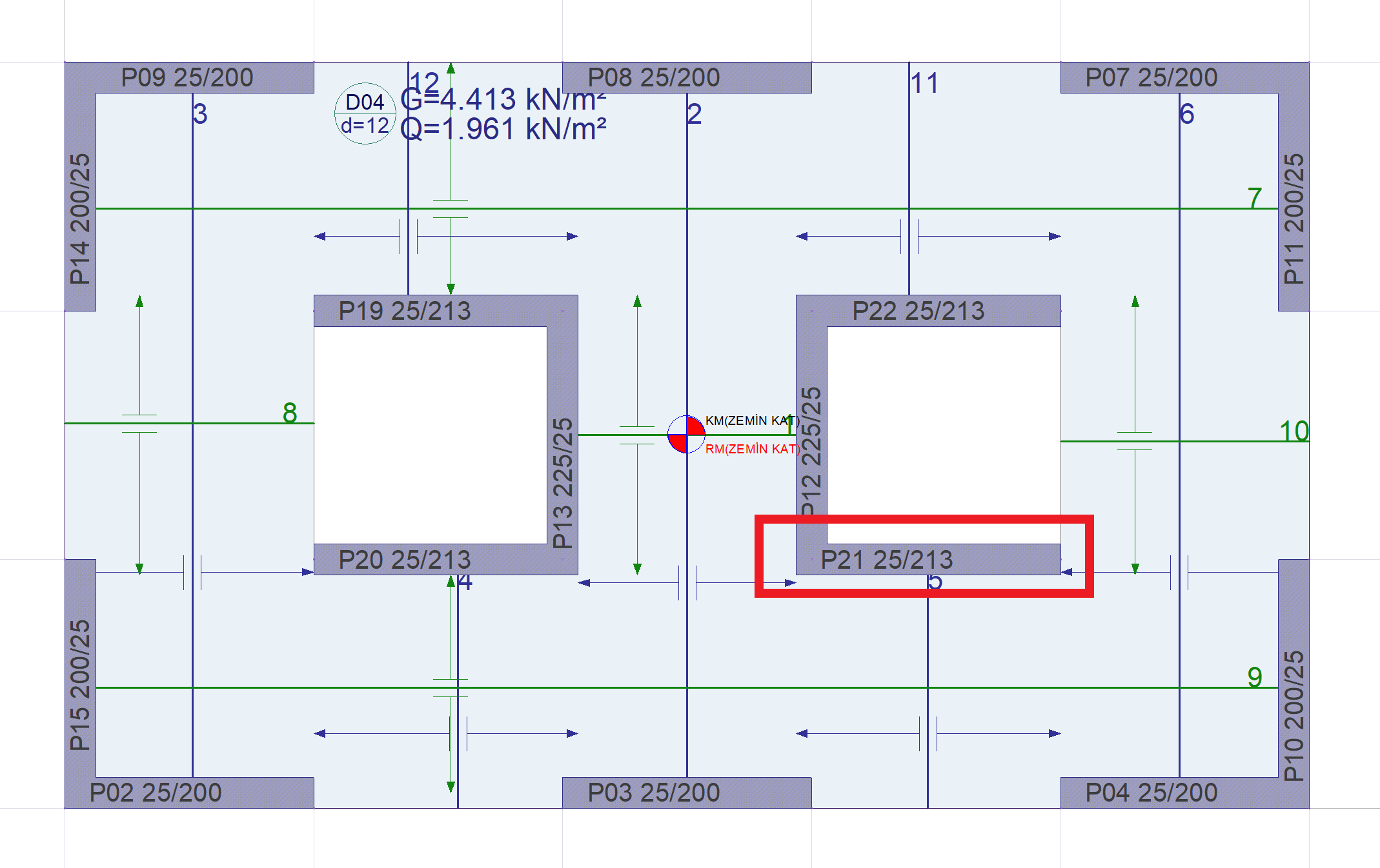
In the sample project, the earthquake force to be transferred from the floor to the P21 curtain arm located on the Ground Floor in a strong direction will be calculated. The calculation will be shown under the effect of G '+ Q' + Ex'-0.3Ey '+ 0.3Ez load combination.
Material: C25 / S420 reinforcement design yield strength, f yd = 420 / 1.15 = 365.22 MPa
Strength Excess Coefficient, D = 2.5
As mentioned in TBDY Section 7.11.5 , the earthquake force (DV d ) to be transferred to the wall arm in a strong direction , the earthquake effects calculated taking into account the Resistance Excess Coefficient D at the lower section of the floor level (DV d, i ) and at the upper section of the floor level (DV d, i). +1 ) is calculated as the difference of shear forces occurring.
DV d = DV d, i - DV d, i + 1
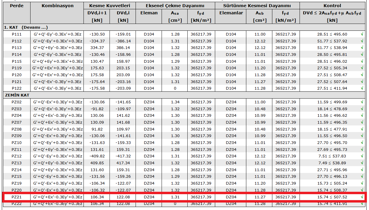
Ground Floor P21 at the upper end of the curtain arm; Under the effect of G '+ Q' + Ex'-0.3Ey '+ 0.3Ez load combination, the shear force DV d is calculated as i = 122.08 kN under the combined effect of earthquake loads calculated by taking into account the Resistance Excess Coefficient D.
The first normal floor is at the lower end of the P21 curtain arm; Under the effect of G '+ Q' + Ex'-0.3Ey '+ 0.3Ez load combination, the shear force DV d is calculated as i + 1 = 106.34 kN under the combined effect of the earthquake loads calculated by taking into account the Resistance Excess Coefficient D.
In this case, the earthquake force to be transferred to the curtain arm in a strong direction;
DV d = DV d, i - DV d, i + 1 = 122.08 - 106.34 = 15.74 kN
was found as.
The reinforcement layout of the slab is shown in the picture below. According to this reinforcement layout, Transfer Reinforcement Area, A hr and Connection Reinforcement Area A sb are calculated as shown below.
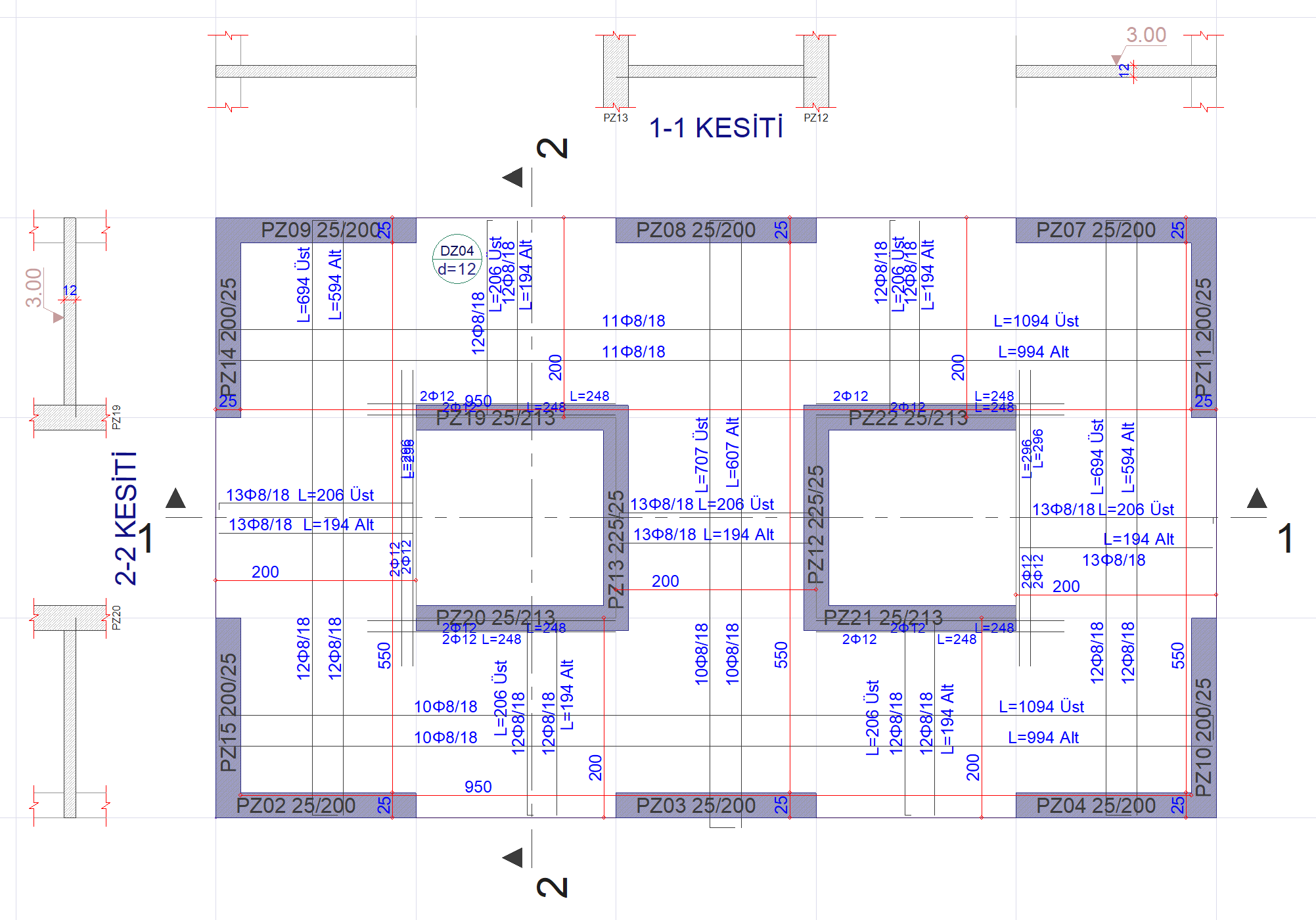
Transfer Reinforcement Area, A sa is the area of reinforcement that is stuck to the wall in a strong direction from both sides and remains from the required bending strength. It can be considered that slab reinforcements 8/18, which are connected to the PZ21 curtain from the strong and weak axis and that meet the overlap length condition, are stuck in the strong axis of the wall. In this case, there will be approximately 6 pieces of Φ8 reinforcement at 1 m. Since these reinforcements are at the top and bottom, there will be a total of 12 reinforcements of 1 m length. In this case, the area of reinforcement obtained for 1m length is;
12 * (π * (8 2 /4)) = 603,186 mm 2 is located in.
In the program, from the finite element results (perspective screen - analysis display - shell results - flooring - related directional reinforcement), the area of reinforcement required for bending in the slab in the end region of the PZ21 wall arm was read as approximately 0.5 cm 2 / m = 50 mm 2 / m.
In this case, the area of reinforcement that is stuck in the 25 cm thick PZ21 curtain and remaining from the required bending strength;
A h = 0.25 * (603.186 - 50) = 138.29 mm 2 = 1.38 cm 2 .
Connection Reinforcement Area, A sb , is the area of the remaining floor reinforcement that is required for the flexural strength at the curtain slab joint. The floor reinforcement in the combination of PZ21 curtain and slab is 8/18, top and bottom. In this case, it can be assumed that there are a total of 12 reinforcements for 1 m, 6 of which are bottom and 6 pieces. In this case, the area of reinforcement obtained for 1m length is;
12 * (π * (8 2 /4)) = 603,186 mm 2 / m available as.
In the program, from the finite element results, the area of reinforcement required for bending in the PZ21 wall-slab joint was read as approximately 0.3 cm 2 / m = 30 mm 2 / m. In this case, the area of reinforcement remaining from the reinforcement required for bending,
603.186 - 30 = 573 mm 2 / m = 5.73 cm 2 / m.
Considering the length of the curtain arm as 2 m;
A sb = 5.73 * 2 = 11.46 cm 2 .
Drive reinforcement area, A h and connection reinforcement area, the SB sum of the axial tensile strength produced by the network equipment after making (2E h f yd ) and the connection reinforcement formed by shear friction Strength (μ A sb f yd ) The sum DV d shall not exceed.
µ is the cutting friction coefficient. According to TS 500 Table 8.1, it is taken as µ = 1.4 for a cast concrete. However, as stated in Article 7.11.5 of TBDY, the value of µ≤1 will be used, so µ = 1.0.
In this case, the earthquake force control to be transferred from the floor to the P21 curtain arm located on the Ground Floor in a strong direction is done as follows.
DV d = 15.74 kN
2A sa f yd + µA sb f yd = [2 * 138.29 * (365) + 1 * 1146 * (365)] / 1000 = 519.24 kN
Since DV d = 15.74 kN <2A sa f yd + µA sb f yd = 519.24 kN, the force is transferred safely.
Next Topic