
ICONS
A c = Cross-sectional area of the column
f ck = Characteristic compressive strength of concrete
f cd = Design compressive strength of concrete
f yd = Design yield strength of longitudinal reinforcement
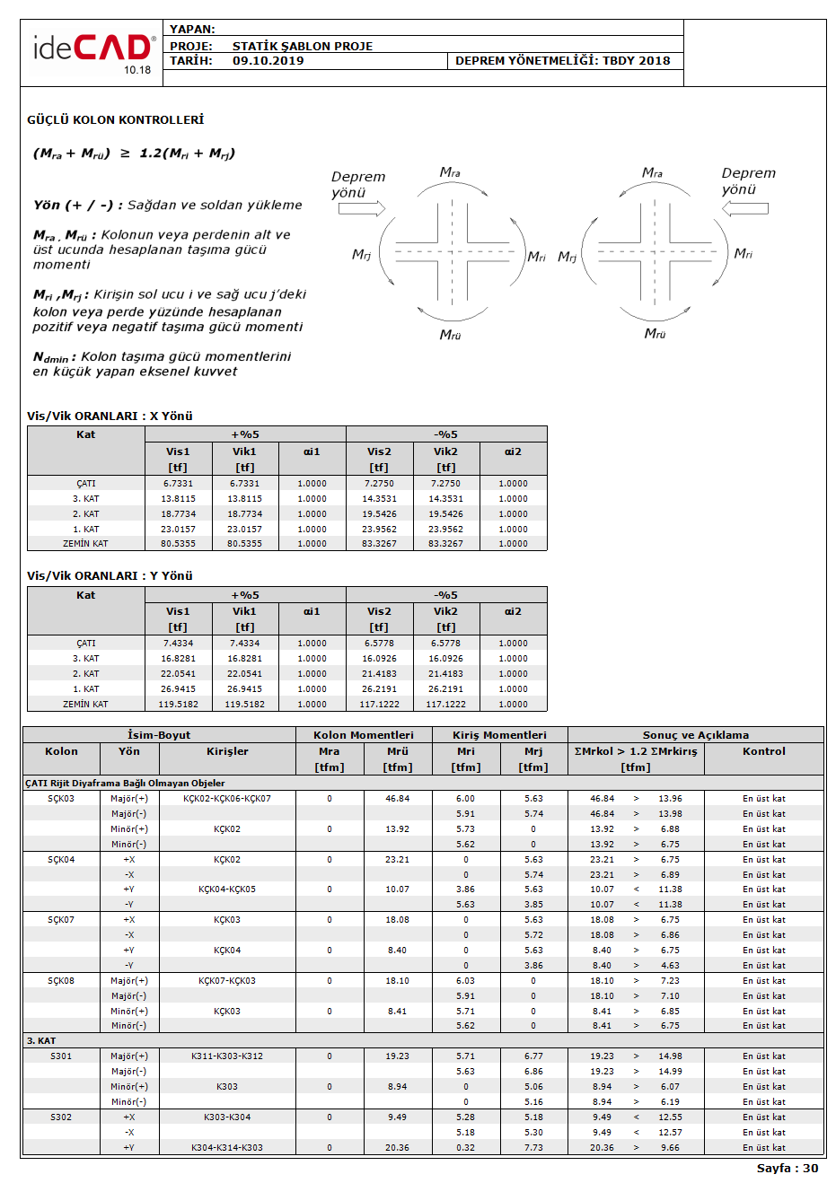
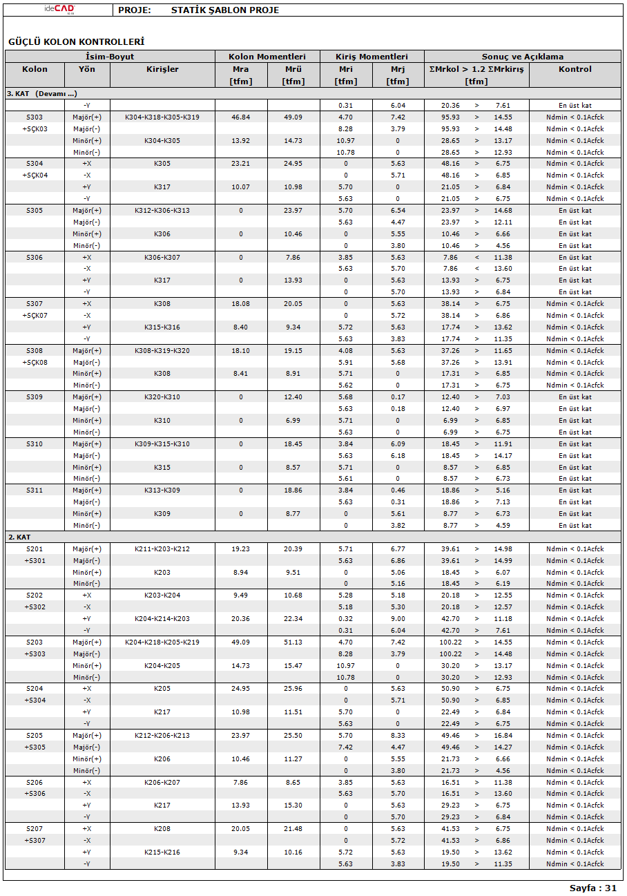
M ra = Bearing strength calculated according to f cd and f yd at the lower end of the free height of the column or wall torque
M r = column or in the upper end of the free height of the curtain for CDs and f yd 'calculated according to the ultimate moment
M r = Moment of positive or negative bearing capacity calculated according to f cd and f yd on the column or wall face at the left end of the beam
M rj = Negative calculated according to f cd and f yd on the column or wall face at the right end of the beam j positive bearing strength moment
N d = Axial force calculated under the combined effect of vertical loads and earthquake loads multiplied by the load factors.
V ik = Sum of shear forces calculated in the direction of the earthquake in all columns on the i'th floor of the building
V is =The sum of shear forces calculated in the direction of the earthquake considered in the columns where (M ra + M rü ) ≥ 1.2 (M ri + M rj ) is provided at both the lower and upper joints of the building. At the ends of the columns meeting the condition N d ≤ 0.10 A c f ck , Eq. Even if (7.3) is not provided, these columns are also not taken into account in the calculation of V is .
Strong column controls are given as a subtitle in the column report.
-
In structural systems consisting of only frames or a combination of walls and frames, it is checked whether the sum of the bearing strength moments of the columns joining each column-beam node is at least 20% greater than the total bearing strength moments of the beams joining that node. (M ra + M rü ) ≥ 1.2 (M ri + M rj )
-
In case of Nd≤ 0.10 A c f ck in both of the columns joining the node point , or at the nodal points of the top floor of single-storey buildings and multi-storey buildings, or if the curtain where the beams are stuck working like a column in a weak direction, it is not considered that the above condition is not fulfilled. Information is written in the control column of the report with the terms Nd≤ 0.10 A c f ck or Top floor .
-
In case of N d ≥ 0.10 A c f ck in one of the columns joining the node point and there are columns that do not satisfy the condition (M ra + M rü ) ≥ 1.2 (M ri + M rj ) in the system, in the earthquake direction considered, in any i'th floor of the building If the condition alpha i = V is / V ik is satisfied, it is allowed not to meet (M ra + M rü ) ≥ 1.2 (M ri + M rj ) in some columns above and / or below the relevant floor .
-
Columns satisfying the condition N d ≤ 0.10 A c f ck can be used in the calculation of V is even if they do not satisfy the condition (M ra + M rü ) ≥ 1.2 (M ri + M rj ) .
-
If the equation alpha i = V is / V ik is met 0.70 <1 / alpha i <1.00 in the interval (M ra + M rü ) ≥ 1.2 (M ri + M rj ), it is The bending moments and shear forces are multiplied by the (1 / alpha i ) ratio.
-
If any floor does not meet the condition, the user will be warned by the program.
-
Information on strong column control in the program is displayed in the Weak Column Information tab in the Column Reinforced Concrete dialog. The columns that do not satisfy the (M ra + M rü ) ≥ 1.2 (M ri + M rj ) condition are marked in the ZK column in the Columns tab in the same dialog .
Next Topic