
Drawing a Stirrup
The ideCAD automatically draws stirrups and crossties for longitudinal reinforcement in columns according to the standards specified in the earthquake regulation. Besides, the user can make stirrup drawing by using his own initiative.
Location of the Stirrup Command
You can access it under the Drawings tab, Reinforcement heading.
Usage Steps
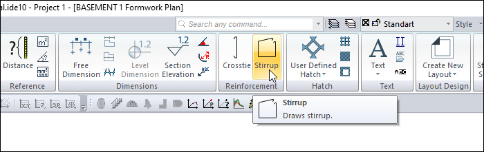
For example, let's cancel the crossties in the left column above and draw stirrups as seen in the right column,
In the column application plan, explode the column with the explode command.
Erase the stirrups.
Click the Stirrup icon in the drawings tab rebar header.
Click on the longitudinal reinforcement circles to which you want the stirrup to be connected (middle bars in the drawing above) sequentially. When you click on the first rebar, stirrups will start to be drawn.
Select the second, third and fourth rebar respectively.
When you choose the first rebar you selected again, your stirrup will be created.
Usage step |
|---|
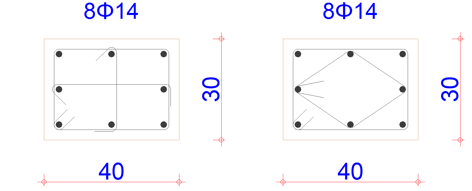
The first version of the column drawing 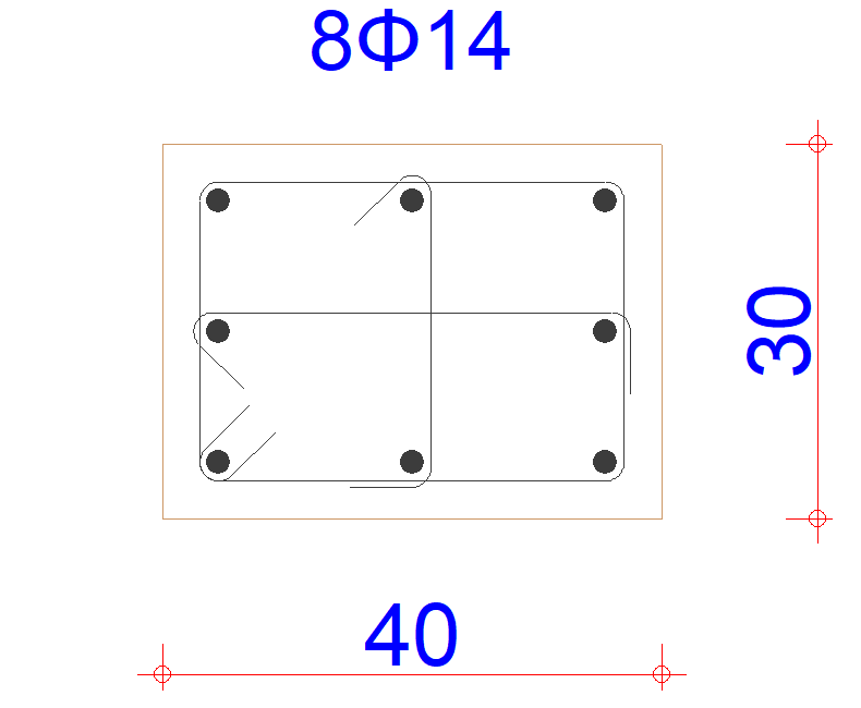 |
Erasing the crossties  |
Choosing the first point for stirrup  |
Selection of the second point  |
Choosing the third point  |
Selection of the fourth point  |
Selecting the first point again and forming the stirrup 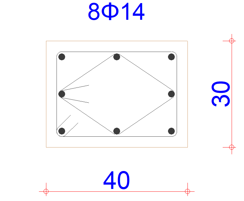 |
Next Topic