
Well Foundation Drawings
Drawings of the well foundation can be prepared with the Well Foundation Drawings command.
Location of the Well Foundation Drawings Command
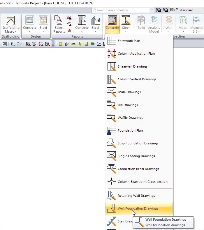
You can access it under the ribbon menu Concrete tab, Create Drawing heading.
Usage Steps
Click on the Well Foundation Drawings icon.
The drawing properties dialog will open. If there is a different situation in this dialog, change the parameters related to the drawing.
When you click the OK button, the well foundation drawing will be created.
General Tab
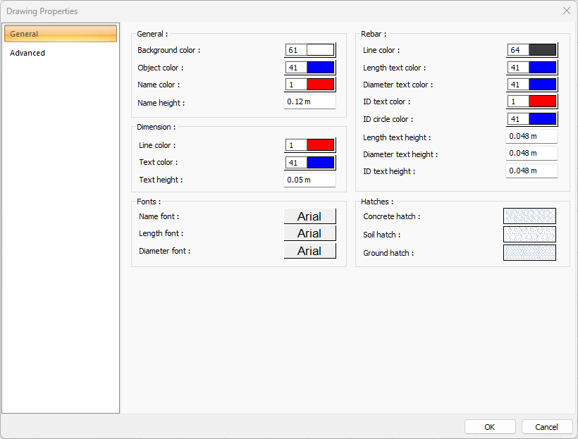
Specifications - General |
Background color  Sets the background color. When the color box is clicked, the appropriate color is selected from the window that opens. |
Object color  Sets the object color. When the color box is clicked, the appropriate color is selected from the window that opens. |
Name color  Sets the name color. When the color box is clicked, the appropriate color is selected from the window that opens. |
Name height  Name height is entered. |
Specifications - Dimensions |
Line color  Sets the measure line color. When the color box is clicked, the appropriate color is selected from the window that opens. |
Text color  Sets the color of the dimension text. When the color box is clicked, the appropriate color is selected from the window that opens. |
Text height  Size text height is entered. |
Specifications - Fonts |
Name font  Name font is selected. |
Length font  The font of the length fonts is selected. |
Diameter font  Diameter font is selected. |
Specifications - Rebar |
Line color  Sets the color of rebar lines. When the color box is clicked, the appropriate color is selected from the window that opens. |
Length text color  Sets the color of the length text. When the color box is clicked, the appropriate color is selected from the window that opens. |
Diameter text color  Sets the color of the diameter text. When the color box is clicked, the appropriate color is selected from the window that opens. |
ID text color  Sets the color of the ID text. When the color box is clicked, the appropriate color is selected from the window that opens. |
ID circle color  ID sets the color of the circle. When the color box is clicked, the appropriate color is selected from the window that opens. |
Length text height  Text height is entered. |
Diameter text height  Diameter text height is entered. |
ID text height  ID text height is entered. |
Specifications - Hatches |
Concrete hatch  It is the hatch type that is valid for concrete. Clicking on hatch opens the Hatch Settings dialog. The hatch type is selected from the lookup table in this dialog. |
Soil hatch  It is the hatch type that is valid for the soil. Clicking on hatch opens the Hatch Settings dialog. The hatch type is selected from the lookup table in this dialog. |
Ground hatch  It is the hatch type that is valid for the ground. Clicking on hatch opens the Hatch Settings dialog. The hatch type is selected from the look-up table in this dialog. |
Advanced Tab
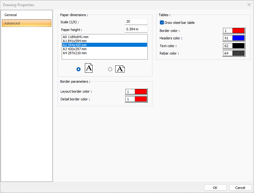
Specifications |
|---|
Scale (1/X)  In what scale the drawings will be drawn, that value is entered. |
Paper height  Standard paper sizes can also be selected, and any paper size value can be entered. |
Standard paper sizes 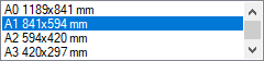 Standard paper sizes are listed. The layout size can be selected from the list, as well as the layout dimensions can be determined by entering the width and height values. |
Vertical/Horizontal use  It is determined whether the layout will be used horizontally or vertically. |
Layout border color  You can select the layout border color from the color palette that appears when you click it. If clicked together with the Shift key, the pen thickness of the relevant color can be adjusted. The pen thickness value entered here is only used in inkjet printers. |
Detail border color  You can select the detail border color from the color palette that appears on the screen when you click it. If clicked together with the Shift key, the pen thickness of the relevant color can be adjusted. The pen thickness value entered here is only used in inkjet printers. |
Draw steel bar table  If checked, steel bar tables are added to the drawing. |
Border color  Sets the color of the border lines. When the color box is clicked, the appropriate color is selected from the window that opens. |
Headers color  Sets the table header color. When the color box is clicked, the appropriate color is selected from the window that opens. |
Text color  Sets the color of text. When the color box is clicked, the appropriate color is selected from the window that opens. |
Rebar color  Sets the color of the rebar. When the color box is clicked, the appropriate color is selected from the window that opens. |
Next Topic