
Node Settings
Turning nodes on and off, radius and color settings are adjusted with the Node Settings command.
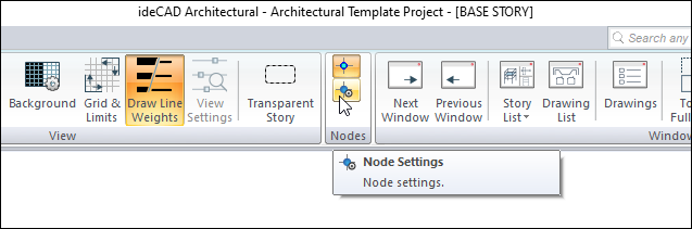
Location of the Node Settings Command
You can access it from the Nodes heading of the ribbon menu View tab .
You can also access the Preferences dialog from the Drawing tab.
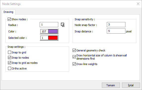
Node Settings Dialog
Specifications |
|---|
Show nodes  It allows the node points to be visible in the plan or not. If checked, nodes are visible in the plan and not visible if not marked. |
Radius  In case the node points are shown, the diameter of the visible in the plan is set on this line. Its unit is pixel. |
Color  In the case where the node points are shown, the color shown in the plan is selected. |
Selected color  In case the nodes of the selected object are shown, the color shown in the plan is selected. |
Node snap factor 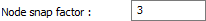 During node selection, the distance to click is set. If the mouse cursor is around the node snap factor near the node, it allows the node to be selected by clicking the left button. |
Snap distance  During the object selection, the distance to be clicked is adjusted. If the mouse cursor is around the object's snap distance setting, you can select the object. The value entered here also affects the difficulty / ease of selection (its unit is pixel). |
Snap to grid  Used for the cursor to catch the intersection points of the grid lines. Mark the line for locking possibility. |
Snap to nodes  Used for the cursor to jump (snap) to nodes. Check the locking facility line. |
Snap to grid as nodes  Check if you want the cursor to catch the grid points while in object mode. |
Ortho active  Check if you want to turn on ortho mode. Vertical mode provides ease of drawing objects at 0 and 90 degrees. |
General geometry check  Mark for automatic general geometry check. It is recommended to keep the line marked in order to immediately avoid possible errors (geometric errors) that may be encountered while drawing. |
Draw horizontal size of column & shearwall dimensions first 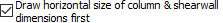 When this option is selected, in places where column and shearwall names are written such as formwork, column application, report, the dimension of the column and shearwall dimensions parallel to the x axis is written first. For example, let's define a column that is 25 vertical and 60 cm horizontal. We can define the ideCAD possibilities as we want by rotating this column. When this option is checked, the column dimensions will be written as 25/60 regardless of how the definition is made. |
Next Topic
Related Topics