
Column Vertical Drawings
With the Column Vertical Drawings command, the vertical column expansions of the project are created.
Location of the Column Vertical Drawings Command
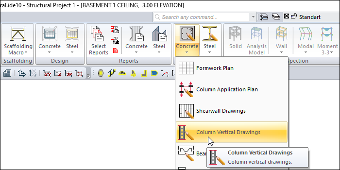
You can access it under the ribbon menu Concrete tab, Create Drawing heading.
Usage Steps
Click the Column Vertical Drawings icon.
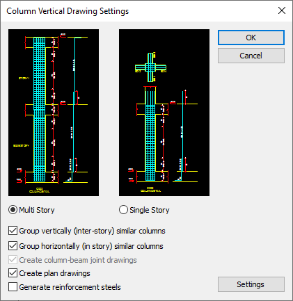
The Column Vertical Drawing Settings dialog will open.
The columns of the working story will be automatically designed according to the scale and layout size specified in the drawing settings. One or more columns can create vertical drawing windows depending on the fit on the sheet. The relevant window can be selected from the list under the Window menu.
In the drawing properties dialog that opens when you click the Settings button, you can make the desired edits and click the OK button.
In the vertical drawings of the column, all column-beam joints, rebars and dimension lines are arranged as a block. You can split the blocks into sub-blocks with the object fragment. In the sub-blocks, again, the object can be divided into lines and writings with explode.
Column Vertical Opening Settings
Specifications |
Multi story 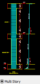 Prepares the vertical column of the columns throughout the whole story. |
Single story 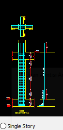 It arranges the vertical drawing of the columns separately for each story. |
Group vertically (inter-story) similar columns  The rebars and dimensions of the columns are compared on a story basis and similar ones are grouped within themselves and given in a single detail. |
Create horizontally (in story) similar columns  The rebars and dimensions of the columns are compared within the layer and similar ones are grouped within themselves and given in a single detail. |
Create column-beam joint drawings  It becomes active when the single story option is selected. It also creates the column-beam junction area detail above each detail in column openings. |
Create plan drawings  If checked, the plan drawing is created. |
Generate reinforcement steels  If marked, the reinforcement steel is drawn. |
Settings  Opens the dialog where drawing properties can be set. |
Settings - Drawing Properties
General Tab
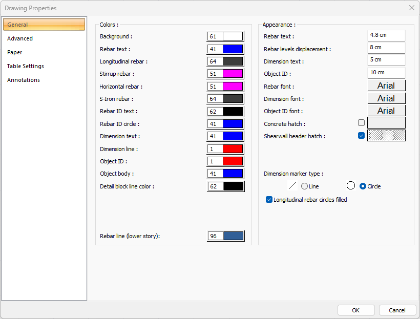
Specifications |
Background color  Sets the background color. When the color box is clicked, the appropriate color is selected from the window that opens. |
Rebar text  Sets the color of the rebar text. When the color box is clicked, the appropriate color is selected from the window that opens. |
Longitudinal rebar  Sets the longitudinal rebar color. When the color box is clicked, the appropriate color is selected from the window that opens. |
Stirrup rebar  Sets the stirrup rebar color. When the color box is clicked, the appropriate color is selected from the window that opens. |
Horizontal rebar  Sets the horizontal rebar color. When the color box is clicked, the appropriate color is selected from the window that opens. |
S-Iron rebar  Sets the s-iron rebar color. When the color box is clicked, the appropriate color is selected from the window that opens. |
Rebar ID text  Adjusts the color of the rebar ID text. When the color box is clicked, the appropriate color is selected from the window that opens. |
Rebar ID circle  Adjusts the color of the rebar ID circle. When the color box is clicked, the appropriate color is selected from the window that opens. |
Dimension text  Sets the dimension text color. When the color box is clicked, the appropriate color is selected from the window that opens. |
Dimension line  Sets the dimension line color. When the color box is clicked, the appropriate color is selected from the window that opens. |
Object ID  Sets the color of the object ID. When the color box is clicked, the appropriate color is selected from the window that opens. |
Object body  Sets the color of the object body. When the color box is clicked, the appropriate color is selected from the window that opens. |
Detail block line color  Sets the line color of the detail block. When the color box is clicked, the appropriate color is selected from the window that opens. |
Rebar line (lower floor)  Adjusts the color of the lines showing the rebar in the lower story. When the color box is clicked, the appropriate color is selected from the window that opens. |
Specifications - Appearance |
Rebar text  The height of the rebar text is entered. |
Rebar levels displacement  The distance between the two rebar texts is entered. |
Dimension text  The height of the dimension text is entered. |
Object ID  The height of the object ID is entered. |
Rebar font  The rebar font is selected. |
Dimension font  Dimension font is selected. |
Object ID font  Object ID font is selected. |
Concrete hatch  It is the hatch type that is valid for concrete. Clicking on hatch opens the Hatch Settings dialog. The hatch type is selected from the look-up table in this dialog. |
Shearwall header hatch  It is the hatch type valid for shearwall heading. Clicking on hatch opens the Hatch Settings dialog. The hatch type is selected from the look-up table in this dialog. |
Dimension marker type 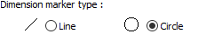 The dimension marker type is selected. |
Longitudinal rebar circles filled  When the option is selected, the inside of the longitudinal rebar circles are filled. |
Advanced Tab
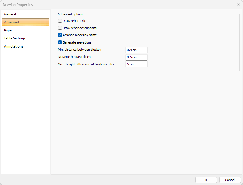
Specifications |
|---|
Draw rebar ID’s  If checked, rebar ID’s are shown in the drawings. If not checked, it will not be displayed. |
Draw rebar descriptions  If checked, the rebar descriptions are shown in the drawings. If not checked, it will not be displayed. |
Arrange blocks by name  In the expansions, the objects are marked if they want to be placed according to the element names while placing the layout on the layout. If not marked, the expansions are placed according to the principle of the most economical use of the layout. The name is ignored. Names can be mixed. Object names; For example, if beam is mentioned, they are names such as K101, K104 etc. The expansion is beam opening, foundation opening, rib opening, etc. |
Generate elevations  If checked, elevations are shown in the drawings. If not checked, it will not be displayed. |
Min. distance between blocks  Minimum horizontal distance between blocks is entered. The block is each opening itself, with its rebars, sections and dimensioning. |
Distance between lines  Minimum vertical distance between blocks is entered. The block is each opening itself, with its rebars, sections and dimensioning. |
Max. height difference of blocks in a line  The maximum height difference of each block in the row (vertical direction) is entered. If the difference between the height of the block to be placed and the height of the previously placed block is smaller than the value entered on this line, the layout is made. If it is large, no settlement is made. It is left to the next row. The block is each opening itself, with its rebars, sections and dimensioning. |
Paper Tab
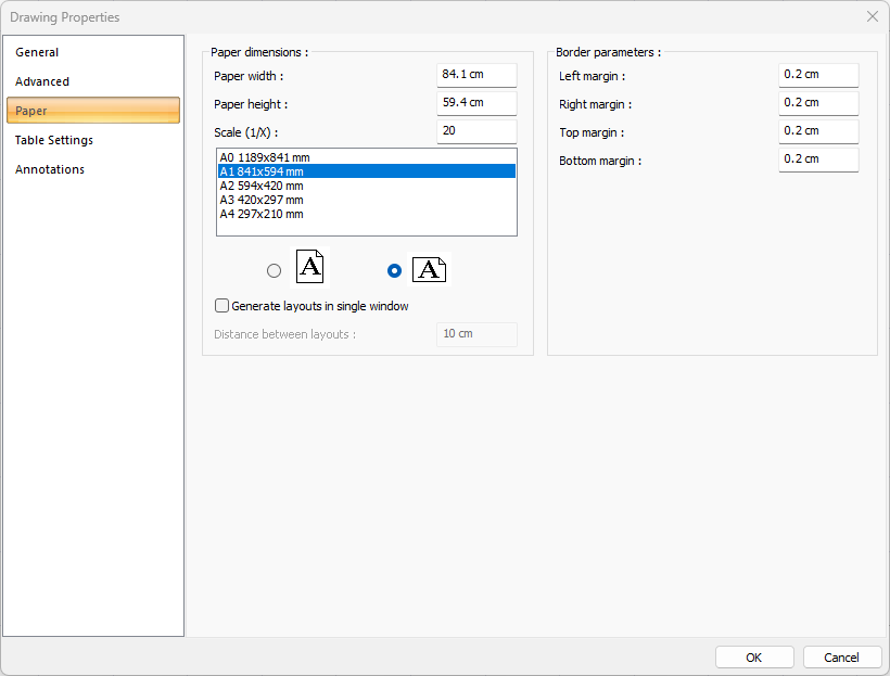
Specifications |
|---|
Paper width  As well as selecting the standard paper sizes, any paper width value can also be entered. |
Paper height  Standard paper sizes can also be selected, and any paper size value can be entered. |
Scale (1/X)  In what scale the expansions will be drawn, that value is entered. |
Standard paper sizes 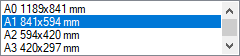 Standard paper sizes are listed. The layout size can be selected from the list, as well as the layout dimensions can be determined by entering the width and height values. |
Vertical/Horizontal use  It is determined whether the layout will be used horizontally or vertically. |
Generate layouts in single window  By selecting the option, layouts are created in a single window. |
Distance between layouts  The distance between the layouts to be created side by side is entered. |
Left margin  The distance of the layout border from the axis border to the left side is entered. |
Right margin  The distance from the axis border to the right side of the layout border is entered. |
Top margin  Enter the distance from the axis border to the top side of the layout border. |
Bottom margin  The distance from the axis border to the bottom side of the paper border is entered. |
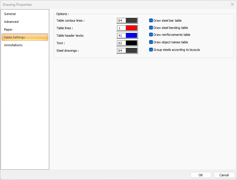
Table Settings Tab
Specifications |
|---|
Table contour lines  Sets the color of the table contour lines. When the color box is clicked, the appropriate color is selected from the window that opens. |
Table lines 
Sets the color of the table lines. When the color box is clicked, the appropriate color is selected from the window that opens. |
Table header texts  Sets the color of the table header texts. When the color box is clicked, the appropriate color is selected from the window that opens. |
Text  Sets the color of table text. When the color box is clicked, the appropriate color is selected from the window that opens. |
Steel drawing  Sets the color of the steel drawing. When the color box is clicked, the appropriate color is selected from the window that opens. |
Create steel bar table  If marked, the rebars are divided into types and a table is created indicating the number, diameter, length, type and weight, and the rebar quantity is shown in the drawing. 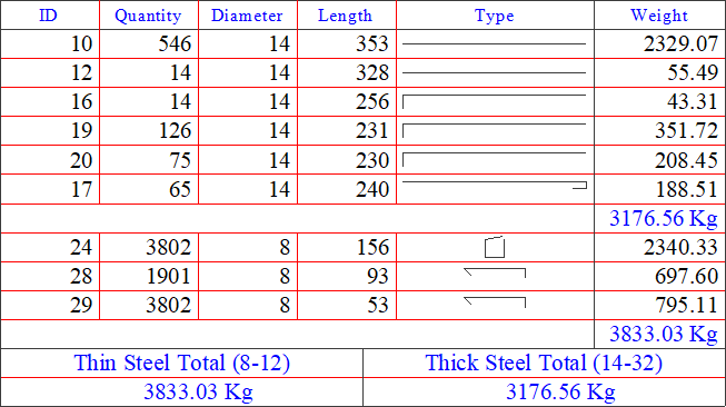 |
Draw steel bending table  If checked, the rebars are divided into bending types and a table is created indicating the number, diameter, length and type, and the bend is shown in the drawing. |
Draw reinforcement table  If checked, the reinforcement table is created and shown in the drawing. |
Draw object names table  If checked, the object names table is created and shown in the drawing. |
Group steels according to layouts  If checked, the steels are grouped according to the layout and shown in the drawing. |
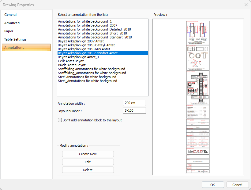
Annotations Tab
Specifications |
|---|
Select an annotation from the list  Defined annotations are listed. |
Preview 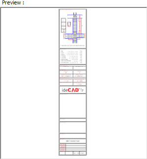 There is a preview of the annotation selected from the list. |
Annotation width  Annotation width is determined. |
Layout number  The layout number is determined. |
Don’t add annotation block to the layout  If it is checked, annotation will not be added to the layouts. |
Create New  The new annotation is created. |
Edit  The annotation is edited. |
Delete  The annotation is deleted. |
Next Topic