
Analysis Settings
In the analysis settings dialog, regulation options, load safety-related parameters, criteria covering the foundation and the overall structure are specified and changed. In the analysis settings dialog, all parameters have default values and these values are arranged with criteria in accordance with the regulation. It is appropriate to change these settings according to the build of your model. It is your responsibility to know the parameters in this dialog and choose the appropriate options for your model. It is recommended that you enter the values in this dialog by using the Earthquake Regulation Wizard, but it is also possible to manipulate the values manually.
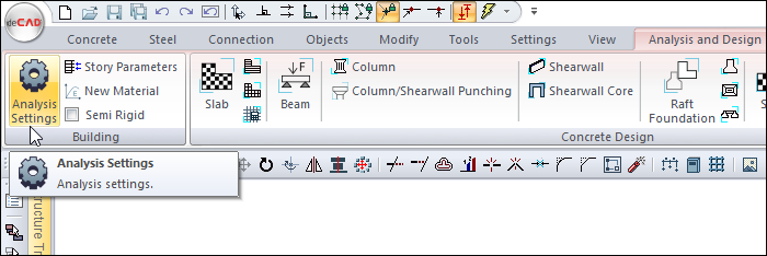
Location of Analysis Settings Dialog
The analysis settings dialog opens automatically when you analyze for the first time.
Analysis Settings can be opened by clicking the Analysis Settings icon in the Analysis and Design menu of the Ribbon Menu.
General Tab
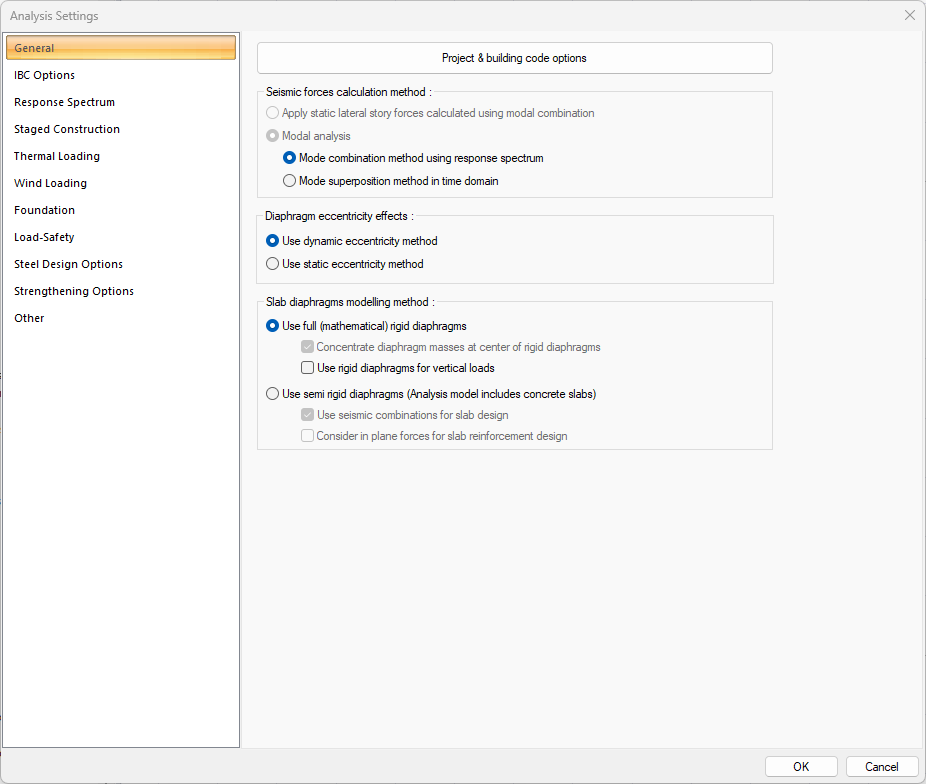
Specifications |
|---|
Project & building code options  Country, unit and code selections are made. By clicking the button, you will be connected to the project wizard. |
Seismic forces calculation method 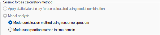 Select one of the seismic forces calculation method from the options. |
Use dynamic eccentricity method 
It is the eccentricity effect in which the story mass centers are calculated by dynamic analysis method by shifting +5% and -5% in both directions. |
Use static eccentricity method  It is the method in which the eccentricity effect is calculated by the seismic load acting on the story mass center. |
Slab diaphragma modeling method 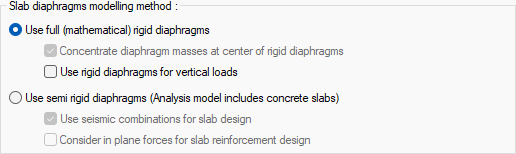 Choose from semi or full rigid diaphragm options. |
Concentrate diaphragm masses at center of rigid diaphragm  It becomes effective when a full rigid diaphragm is selected. When marked, the total mass of the objects belonging to the rigid diaphragm in dynamic analysis is impacted at the center of gravity of the rigid diaphragm as point mass. |
Use rigid diaphragm for vertical loads  It becomes effective when a full rigid diaphragm is selected. If this option is canceled, the structure is considered to be non-diaphragm during vertical calculation. |
Use seismic combination for slab design  It becomes effective when semi rigid diaphragm is selected. In the semi rigid diaphragm solution, slabs are solved together with the structure and therefore earthquake effects are also present in the slab elements. If this option is selected, the effects caused by earthquakes are also taken into account in the slab design. Combinations of earthquakes with vertical load combinations can also be effective in reinforcement design. |
Consider in plane forces for slab reinforcement design  It becomes effective when semi rigid diaphragm is selected. When the option is selected, designs are made according to in plane tensile and pressure forces in all loading situations in slabs. |
Options Tab
Specifications |
|---|
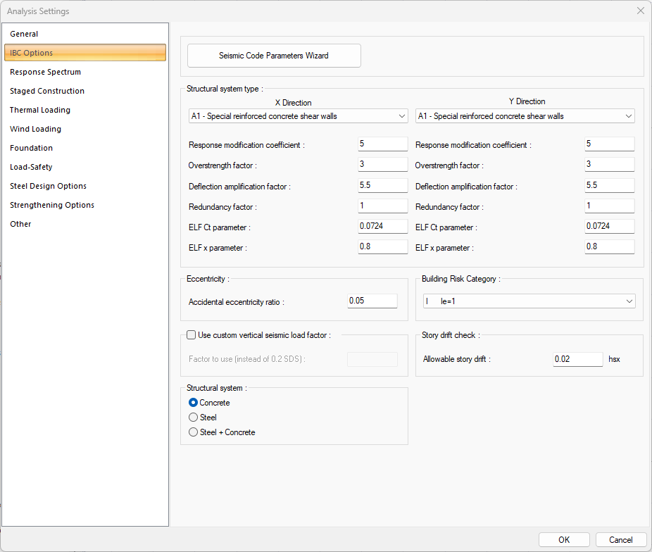
Seismic Code Parameters Wizard  It displays the analysis settings wizard where the parameters specific to IBC are determined step by step. On the wizard screen, you can assign the site class, risk category, horizontal and vertical response spectrum, seismic design category, stories, stories, structural system, diaphragm, structural system type to be used. |
Structural system type  The type of structural system for X and Y direction is selected in accordance with the design of the building. |
Response modification coefficient  It is the response modification coefficient value. This row is automatically refreshed when the structural system type is chosen. |
Overstrength factor  It is the strength excess coefficient value. This row is automatically refreshed when the structural system type is chosen. |
Deflection amplification factor  It is the deflection amplification factor value. This row is automatically refreshed when the structural system type is chosen. |
Redundancy factor  It is the redundancy factor value. This row is automatically refreshed when the structural system type is chosen. |
ELF Ct parameter  It is the ELF Ct parameter. This row is automatically refreshed when the structural system type is chosen. |
ELF x parameter  It is the ELF x parameter. This row is automatically refreshed when the structural system type is chosen. |
Accidental eccentricity ratio 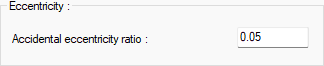 The eccentricity ratio to be used during the analysis is given as a percentage. |
Use custom vertical seismic load factor  If checked, the custom vertical seismic load factor which entered in "factor to use (instead of 0.2 SDS)" line is used. |
Structural system 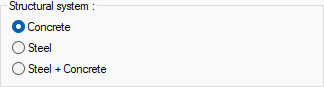 If the building block consists of only concrete elements, Concrete; if it consists of only steel elements, Steel; Steel + Concrete option is selected if it consists of concrete and steel elements. |
Building Risk Category 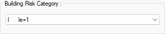 Building risk category value is selected from the list according to the purpose of use of the building. |
Story drift check 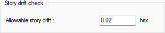 Allowable story drift value is entered. |
The settings in this tab vary depending on the selected codes. You can access detailed settings according to codes here.
Response Spectrum Function Tab
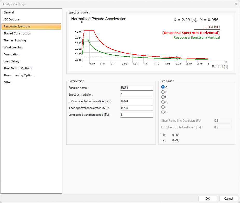
The parameters used in the spectrum can be determined with the wizard for analysis settings, the parameters in this line are automatically refreshed when the wizard is used. Also, the parameters in the dialog can be changed.
In codes where the wizard is inactive, the parameters for the response spectrum are set manually.
Specifications |
|---|
Spectrum curve 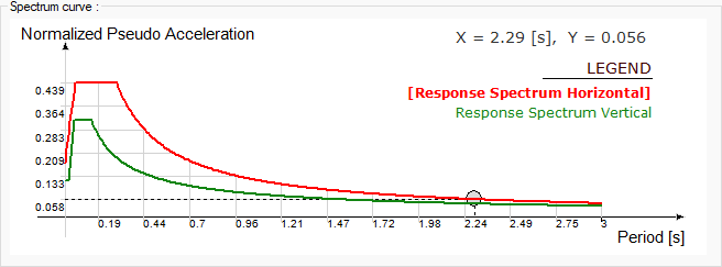 The spectrum curve resulting from the settings is shown. |
Parameters 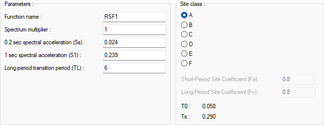 The parameters used in the spectrum can be determined with the wizard for analysis settings, the parameters in this line are automatically refreshed when the wizard is used. Also, the parameters in the dialog can be changed. In codes where the wizard is inactive, the parameters for the response spectrum are set manually. |
The settings in this tab vary depending on the selected codes. You can access detailed settings according to codes here.
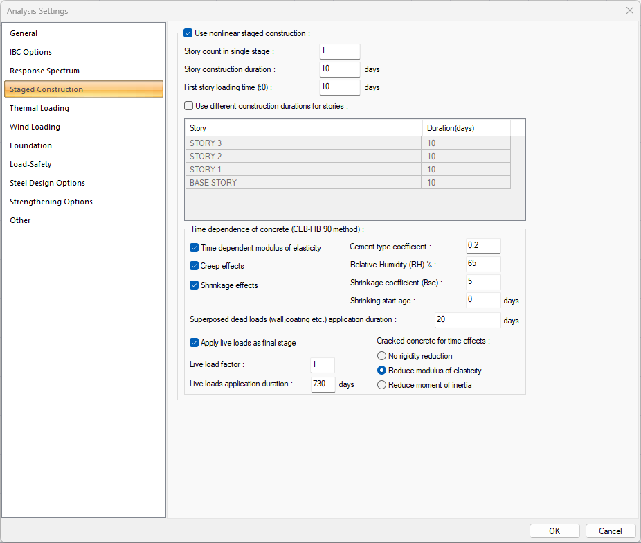
Staged Construction Tab
Specifications |
|---|
Use nonlinear staged construction  Activates the progressive construction calculation for the model whose data is entered. |
Story count in single stage  In this option, the number of story to be considered in single stage is entered. For example, if we give this value 1 for a 10-storey building: For the stage where self and self weights exist, the number of steps = 1st story, 2nd story, 3rd story ..... 8th story, 9th story, 10th story (10th stage); loading in 10 total steps. Loading at the 10th stage for the stage where wall and coating loads exist ... The stage where there are moving loads, loading at the 10th stage ... For example, if we give this value 2 for a 10-storey building: For the stage where self and self weights exist = 1st and 2nd story (1st stage), 3rd and 4th (2nd stage), 5th and 6th (3rd stage), 7 and 8th story (4th stage). stage), 9th and 10th story (5th stage); loading in 5 steps in total. It is the 5th stage loading for the stage where wall and cladding loads exist. The stage in which there are live loads is loading in the 5th stage. |
Story construction duration  If the construction times of the stories are the same, the construction (construction) time of the story is entered in days in this line. For example, if you give 10 days in a 10-story building, it means that each story will be built in 10 days. It means that the construction period of all stories will be from 10 days to 100 days. If the construction times of the stories will be different, the "Use different construction durations for stories" option on the bottom line is checked. |
First story loading time (t0)  Time is given to start the second story construction. |
Use different constructiondurations for stories 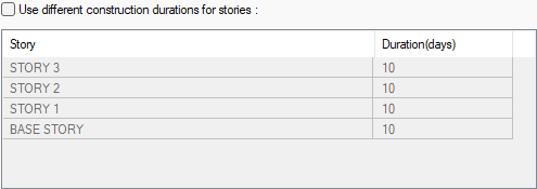 When marked, the construction times of each floor are given in days. If the construction times of the floors will be the same, you can use the "Stage construction time" line above instead of marking this line. |
Time dependence of concrete (CEB-FIB 90 method)  The time dependent of concrete are options that make it stand out. |
Time dependent modulus of elasticity  Check this option to take into account the effects caused by the change in the modulus of elasticity of the concrete during construction. |
Creep effects  Check this option to take into account the effects of strain during construction. |
Shrinkage effects  Check this option to consider impacts from shrinkage during construction. |
Cement type coefficient  It is the cement type coefficient value used when calculating the strength of concrete over time. |
Relative Humidity (RH) %  Give the percentage of humidity of the environment where the building is located. |
Shrinkage coefficient (Bsc)  Bsc is given, which is a coefficient depending on the type of cement. |
Shrinking start age  Give the expected time for the concrete to harden. |
Superposed dead loads (wall, coating, etc.) application duration  In this row, give the time that will pass for the phase where wall and pavement loads exist.
|
Apply moving loads in the final stage 
This option determines whether the 3rd stage will be done or not. |
Live load factor  Live load coefficient to be applied in the phase of live loads is given. |
Live loads application duration  In this line, the time to pass for the phase in which the live loads exist is given. |
Cracked concrete for time effects 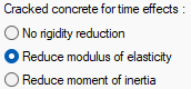 Select the appropriate option for stiffness reduction. If no rigidity reduction is selected, no rigidity reduction is made. If reduce modulus of elasticity is selected, the stiffness reduction is applied by reducing the modulus of elasticity. If the reduce moment of inertia is selected, the stiffness reduction is applied by reducing the inertia modulus. |
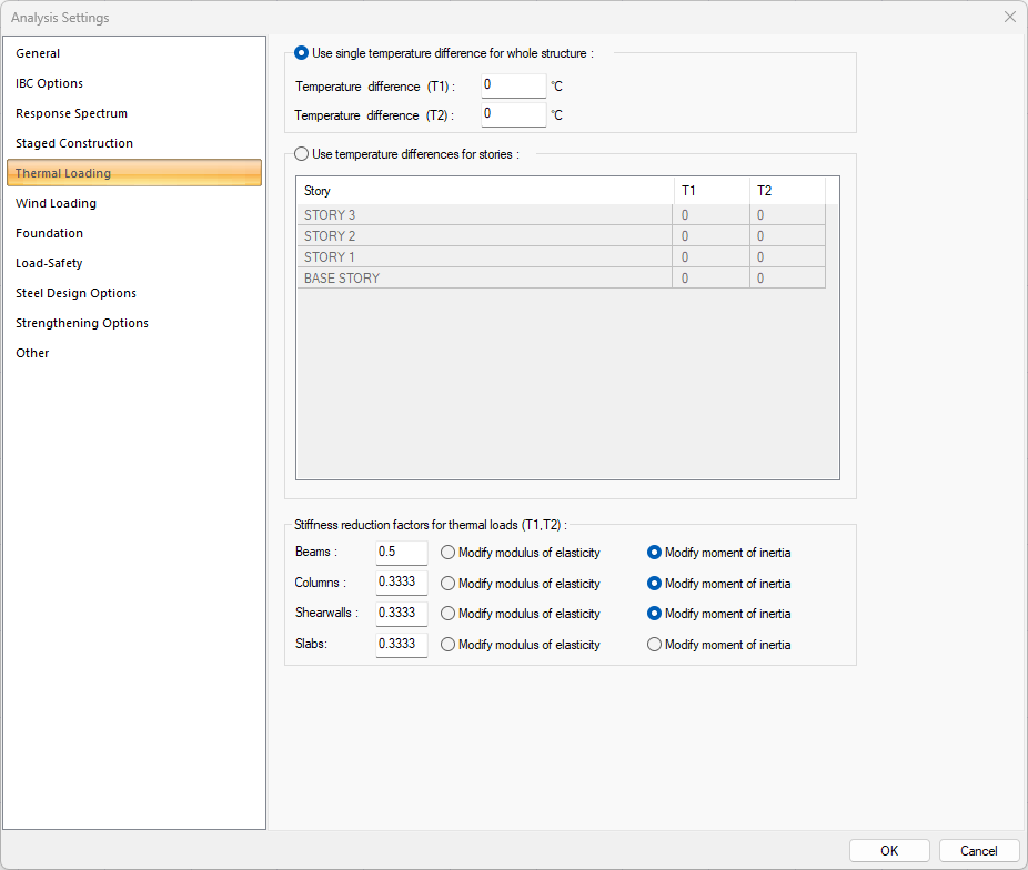
Thermal Loading Tab
Specifications |
|---|
Use single temperature difference for whole structure  This option is checked to take into account the same temperature difference for the whole building. |
Temperature difference (T1) 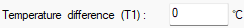 The temperature difference value that will be taken as basis in T1 temperature loading is given. |
Temperature difference (T2) 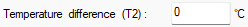 The temperature difference value to be taken as basis in T2 temperature loading is given. |
Use temperature differences for stories 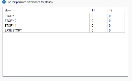 This row is clicked to take into account the temperature differences for each floor separately and the T1 and T2 loading temperature values are given for each floor in T1 and 2 columns. |
Stiffness reduction factors for thermal loads (T1, T2)  In the thermal calculation, reduction factors that determine the stiffness of the cracked element are entered. Separate values can be given for beams, columns, shearwalls and slabs. Modify modulus of elasticity If marked, the reduction coefficient given on the side is multiplied by the modulus of elasticity of the element. Ecr = x.Ec Ec = Element elasticity module x = Reduction factor Knows Icr = elasticity modulus of the cracked element Modify moment of inertia If marked, the reduction coefficient given on the side is multiplied by the element's moment of inertia. Icr = x.Ic Ic = Element moment of inertia x = Reduction factor Icr = Cracked section moment of inertia |
Wind Loads Tab
Specifications |
|---|
Generate wind loads for sheetings (TS498)  If this option is selected, it is calculated according to the principles given in article 11 of TS498 and is affected by the structure depending on the steel coating surfaces. Below, give the structure type, normal or tower type structure. |
Normal type building  For the calculation of wind load affecting the coatings, the wind load is calculated depending on the type of structure determined according to the height limit specified in the regulations. Check this option if your building type is the normal building type. |
Tower type building  For the calculation of wind load affecting the coatings, the wind load is calculated depending on the type of structure determined according to the height limit specified in the regulations. Check this option if your building type is the normal building type. |
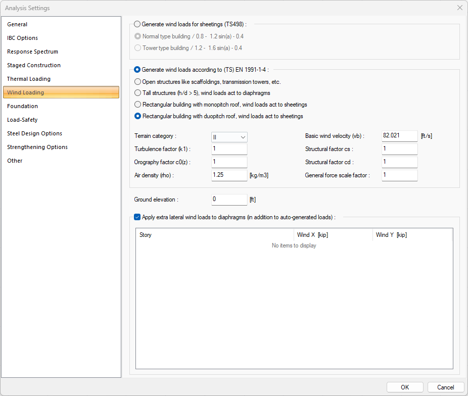
Generate wind loads according to (TS) EN 1991-1-4:  Wind loads are calculated according to TS EN 1991-4. When the option is selected, the settings become active. |
Open structures like scaffoldings, transmission towers, etc.  Wind loads are calculated for structures such as scaffoldings and transmission towers. |
Tall structures (h/d>5), wind loads act to diaphragms  Wind loads are calculated for tall structures where wind loads affect the diaphragms. |
Rectangular building with monopitch roof, wind loads act to sheetings  Wind loads are calculated for rectangular structures with monopitch roofs, where wind loads act on the sheetings. |
Rectangular building with duopitch roof, wind loads act to sheetings  Wind loads are calculated for rectangular structures with duopitch roofs, where wind loads act on the sheetings. |
Terrain category  It is the category selected in Table 4.1 in accordance with the conditions specified in Article 4.3.2 of TS EN 1991-1-4. |
Turbulence factor (k1)  It is the k1 coefficient entered in accordance with article 4.4 of TS EN 1991-1-4. |
Orography factor c0(z)  It is the orography coefficient specified in TS EN 1991-1-4 article 4.3.3. |
Air density (rho)  It is the air density value specified in TS EN 1991-1-4 article 4.5. |
Basic wind velocity (vb)  According to TS EN 1991-1-4, in terrain category II, the basic wind velocity value defined as a function of any part of the year and wind direction at a height of 10 meters above ground elevation is entered. |
Structural factor cs  It is the structural coefficient value specified in TS EN 1991-1-4 Section 6. |
Structural factor cd  It is the structural coefficient value specified in TS EN 1991-1-4 Section 6. |
General force scale factor  It is the scale coefficient used in wind pressure calculation. |
Ground elevation  The ground elevation value used in wind calculation is entered. |
Apply extra lateral wind loads to diaphragms  For steel and concrete structures, it allows the wind loads to be calculated by the user in systems with rigid diaphragms and to affect the rigid diaphragm in the model. |
Story These are the story numbers and names of the stories where rigid diaphragms are located. |
Wind X It is the wind force acting on the rigid diaphragm in the X direction. |
Wind Y It is the wind force acting on the rigid diaphragm in the Y direction. |
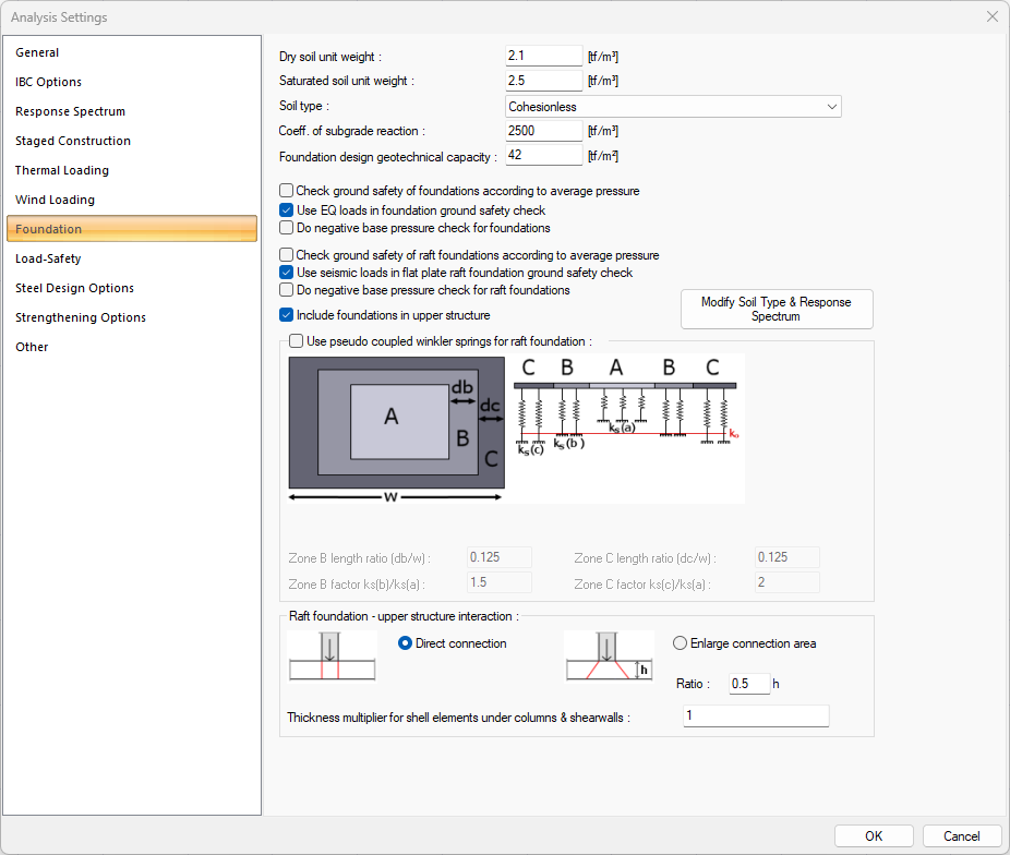
Foundation Tab
Specifications |
|---|
Dry soil unit weight  The unit volume weight of dry soil is entered. |
Saturated soil unit weight  The unit volume weight of the water-saturated soil is entered. |
Soil type  The soil type is determined by choosing one of the options of cohesionless, cohesive (soft) and cohesive (hard). |
Coeff. of subgrade reaction  Subgrade reaction coefficient value is entered. Average bedding coefficient (Ko t / m3) values according to the soil type are as follows: Slime; peat Ko <200 Clay plastic Ko = 500 ~ 1000 Clay, semi-hard Ko = 1000 ~ 1500 Clay hard Ko = 1500 ~ 3000 Stuffed soil Ko = 1000 ~ 2000 Sand, loose Co = 1000 ~ 2000; Sand, medium coarse Co = 2000 ~ 5000 Sand, tight Ko = 5000 ~ 10000 Sand-gravel, tight Co = 10000 ~ 15000 Robust shale Co> 50000 Kaya Ko> 200000 |
Foundation design geotechnical capacity  Basic bearing strength is given by design strength. It is determined according to the soil report. |
Check ground safety of foundations according to average pressure  If it is marked, it is checked whether the ground stresses from all loads are averaged and whether it is less than the ground carrying power. |
Use EQ loads in foundation ground safety check  As a result of the foundation analysis, it is marked if it is desired to take earthquake effects into consideration in the foundation bearing capacity control. In this case, all earthquake combinations are also considered in the ground bearing power control. |
Do negative base pressure check for foundations  As a result of the foundation analysis, negative soil stresses may occur. If this option is checked, if there is a fundamental negative stress, the program will give a message of negativity at the end of the calculation. |
Check ground safety of raft foundations according to average pressure  If it is marked, ground bearing strength is checked by taking the average of the ground stresses of all loads in raft floors. |
Use seismic loads in flat plate raft foundation gound safety check  In the non-beam radius, it is marked if it is desired to take earthquake effects into consideration in soil bearing capacity control as a result of the foundation analysis. In this case, earthquake combinations are also taken into account in ground safety control. |
Do negative base pressure check for raft foundations  As a result of the foundation analysis, negative soil stresses may occur. If this option is checked, if there is a fundamental negative stress, the program will give a message of negativity at the end of the calculation. |
Include foundations in upper structure  If marked, raft and continuous foundation systems are solved interactively with the superstructure. The extreme forces caused by foundation collapses are taken into account in the superstructure. If not checked, the superstructure and foundation are solved separately. |
Use pseudo coupled winkler springs for raft foundation 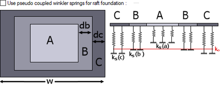 Check this option to use the winkler spring method.  The values of length and spring factors given in the dialog are suitable for the winkler method. However, you can change it if necessary. Give the length ratios to determine the size of the areas, and the B region and C factors as a ratio to the A region arc values. The program will automatically adjust these values to equal the average Ko bed coefficient. |
Raft foundation - upper structure interaction 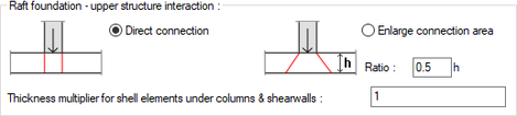 Column - determines the area where the curtain load will be distributed. Vertical element raft connection is provided with rigid elements. The vertical element and basic connection area change according to the option specified in this section. With the direct connection, the load is given to an area equal to the column curtain width. Load distribution is made in an area equal to the ratio given by enlarge the connection area. Area = rate * h Thickness multiplier for shell elements under the column and curtain: Calculations are made by multiplying the finite element thicknesses under the columns and walls with the value entered in the box. |
Load-Safety Tab

Specifications |
|---|
Dead load factor  The value determining how much the dead loads will be increased is entered. |
Live load factor  The value determining how much the live loads will be increased is entered. |
Wall unit weight for Ak calculations  The required wall unit weight is entered for the calculation of the Ak value used in determining the strength irregularity between neighboring floors. |
Use same Ak as upper story on bottom story for B1 (Interstory strength) irregularity check  If the option is selected, the Ak value of the bottom story will be taken the same as the upper story. If you do not want the Ak value to be taken as the same as the upper floor, you can define the Ak value yourself in the "Story parameters" dialog under the "Analysis" menu. |
The settings in this tab vary depending on the selected codes. You can access detailed settings according to codes here.
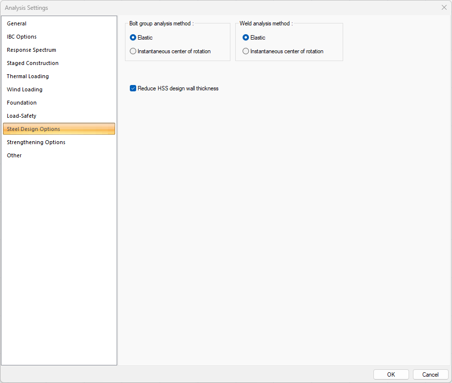
Steel Design Options Tab
Specifications |
|---|
Bolt group analysis method 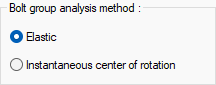 Two main calculation methods, the elastic method or the instantaneous center of rotation methods, can be used in connections subject to eccentric force. Click the option you want to apply. |
Weld analysis method 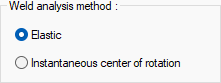 Two main calculation methods, the elastic method or the instantaneous center of rotation methods, can be used in connections subject to eccentric force. Make your choice by clicking on the differences in design philosophy of both methods and the efficiency rates in the combination types used. |
Reduce HSS design wall thickness  It can be selected by the user to take into account the section losses at the production stage of the HSS design wall thickness as prescribed by AISC. |
The settings in this tab vary depending on the selected codes. You can access detailed settings according to codes here.
Strengthening Options Tab
It is the tab that determines the performance analysis options.
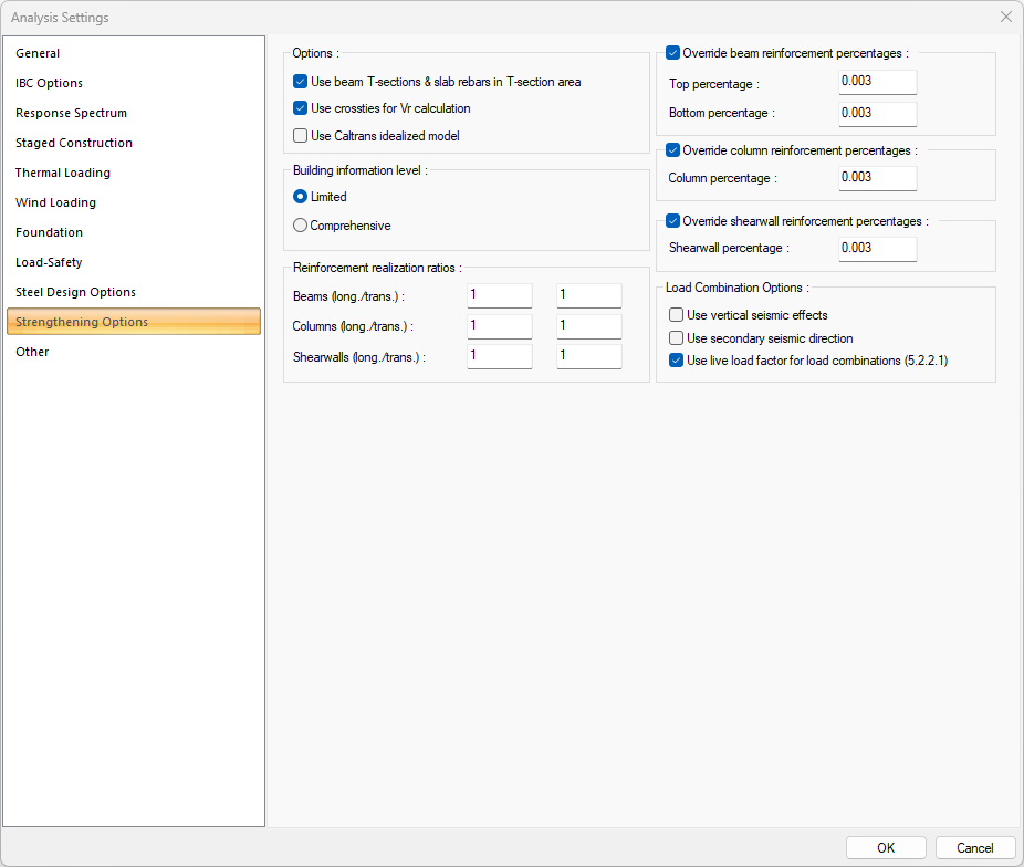
Specifications |
|---|
Use beam table sections  If it is marked, the section of the beam in performance analysis is taken into account as a table section and the reinforcements of the slab in the table are added to the existing reinforcement areas of the beams. If it is not marked, the cross section of the beam is accepted as rectangular section and the reinforcements of the slab in the tray are not included in the existing reinforcement areas of the beams. |
Use crossties for Vr calculation  If marked, the crossties in the column in the performance analysis are added to the column stirrup and taken into account in the column Vr calculation. If not checked, it will not be taken. |
Use Caltrans idealized model  It calculates the yield moment, yield curvature, collapse moment and collapse curvature values in the moment curvature relations used in linear performance analysis calculations according to the idealized model. |
Building information level 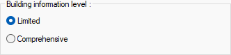 The information level of the building is selected according to the conditions defined in the heading of Collecting Information from Buildings. Knowledge level coefficients by choice; Limited = 0.75 and Comprehensive = 1.00. |
|
Override beam reinforcement percentages 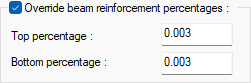 If the option is selected, the beam capacity moments in performance analysis are calculated by taking into account the given percentage values. The upper section refers to the upper region, and the lower to the lower region of the section. |
Override column reinforcement percentages 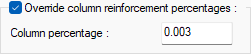 If the option is selected, column capacity moments in performance analysis are calculated by taking into account the given percentage values. |
Override shearwall reinforcement percentages 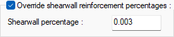 If the option is selected, shearwall capacity moments in performance analysis are calculated by taking into account the given values. |
Reinforcement realization ratio 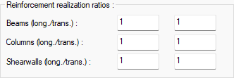 If the reinforcement realization coefficient is entered, the existing reinforcement areas (whether the reinforcement is entered in the reinforced concrete dialog or calculated according to the defined pursuit) are multiplied by these coefficients and the capacity calculations are made according to these values. The transverse and longitudinal reinforcement coefficients can be given separately for beams, columns and walls. |
Use vertical seismic effects  If checked, the combination of vertical earthquake effects (0.30Ez) is also included in the combination of current fixed, live loads and horizontal earthquake effects when creating loading combinations in the performance analysis. |
Use secondary seismic direction  If it is marked, the horizontal earthquake effects in the other direction perpendicular to the earthquake direction taken into account while creating the combinations in the performance analysis are multiplied by 0.3 coefficient and added to the combination. |
Use live load factor for load combination  If checked, live load multiplier in performance analysis is taken as the values entered in the HYK column in the floor general settings. If not checked, moving load multiplier is set to 1. |
Other Tab
Specifications |
|---|
Check project consistency before report generation  If it is desired to list the conformity conditions in terms of regulations while receiving the report, it is marked. If the option is not selected, the program will not notify the project designer at the beginning of the report. |
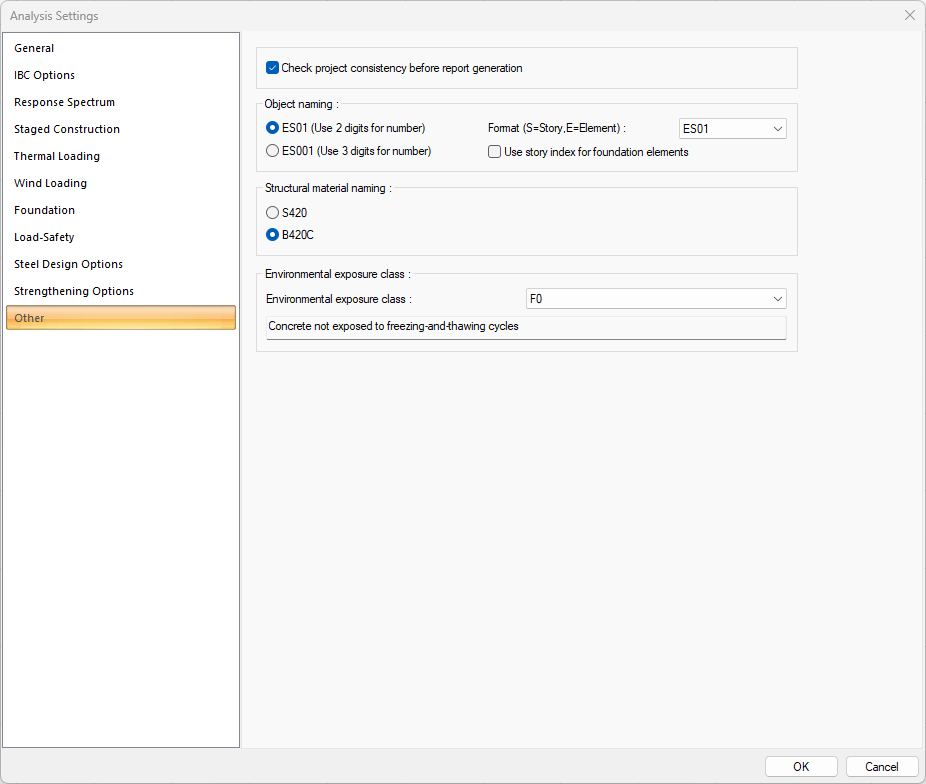
Object naming 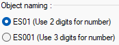 How element naming will be selected. The option selected in this section and the story index entered in the story parameters are used together. For example, let the story index entered in story parameters be 1. Let ES01 option be ticked as naming. S1 name will be considered as S101. If no index was entered in the story general parameters, it would be S01. If the ES001 option is selected in the naming, the name S1 will be considered as S1001. If the index was not entered in the general parameters of the story, this naming would be S001. |
Format  In object naming, the format and story-element ordering is selected from the drop-down list. |
Use story index for foundation elements  Story indices entered in story parameters are also used in the foundation. |
Structural material naming 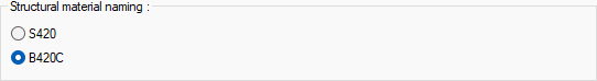 How the naming of the reinforcement material to be seen in the reports is selected. |
Environmental exposure class  Environmental exposure class is selected from the list according to TS EN 206, schedule 1. Information arranged according to the selected class is indicated on the letterheads given in the drawing details. |
Next Topic